Skip to content

博客列表

玩转JetBot自动驾驶 (三)系统安装与配置

robocarstore/173807986231205671

在上一篇文章中,我们完成了JetBot的硬件安装。现在,我们将继续完成JetBot的系统安装和配置。这个过程包括刷写JetBot的SD卡镜像、启动Jetson Nano,并进行一些必要的设置,以确保JetBot能够正确运行。请按照以下步骤完成这些操作。

刷写JetBot镜像(JetBot SD card image)

1,准备好一张64GB+的MicroSD卡

2,下载 JetBot镜像(6.87GB):

百度网盘下载:
链接:https://pan.baidu.com/s/1O8DVn28kY2-5-WBwUMZg9w 密码:dydn

如果提示你烧写的镜像大于你的MicroSD卡,请尝试下载这个镜像,解压缩后63GB:

百度网盘下载:
链接:https://pan.baidu.com/s/1FqeTe4aHYhkEFKxCCEn7XQ 密码:utvz

3,下载SD卡格式化软件「SD Memory Card Formatter

用于正确格式化你的MicroSD卡。
官网下载:https://www.sdcard.org/downloads/formatter/

4,下载SD卡刷写软件「Etcher」

用于把.img的镜像文件写入MicroSD卡
官网下载:https://www.balena.io/etcher/

5,开始烧写

电脑使用读卡器读取MicroSD卡。 robocarstore/173807982431236168

robocarstore/173807983731180869

使用「SD Memory Card Formatter」格式化你的SD卡。如果电脑读取的容量与MicroSD卡标称容量相同时,则可以跳过这个步骤。

打开「Etcher」,选择你所下载的JetBot镜像文件,然后选择要刷写的MicroSD盘符,点击[Flash!],开始刷写。

robocarstore/173807984631182970

如果提示镜像超出MicroSD卡大小的情况,请使用63GB的镜像文件。

这是一个漫长的等待,整个刷写过程小编足足用了3小时多,可能使用USB3.0或者使用Windows系统,刷写时间会更快一些。

6,拔出SD卡

启动Jetson Nano

7,把MicroSD卡插入Jetson Nano

把刚才刷写完成的MicroSD卡插入Jetson Nano的MicroSD卡槽里面

robocarstore/173807986231205671

8,把显示器,键盘鼠标,电源连接上Jetson Nano

注意此时的连接的电源是使用常见的手机充电器,5V电源2A电流的插座电源头进行供电。

robocarstore/173807987531203572

建议在没有连接PIOLED/电机驱动模块的情况下启动Jetson Nano。这样可以确保系统可以正确启动,而不用担心其他硬件所带来不确定问题。在正常启动关机后,再重新连接PiOLED/电机驱动,并仔细检查接线是否正确,然后再通电重新启动。

设置JetBot 连接 本地Wifi

9,开机账号

接通电源后,会见到显示器出现英伟达的LOGO,其实这是一个ubuntu系统,稍等片刻,就能看到输入密码界面,账号密码均是:jetbot

10,进入系统设置好WiFi

在右上角找到网络连接的图标,设置连接你正在使用的WiFi,这样在下次开机的时候JetBot就会自动连接你所设置的Wifi,并把获得的局域网IP显示在PiOLED屏幕上。

11,关机

当你设置好WiFi的时候,可以点击右上角电源图标,点开找到「shutdonw」进行关机。

12,拔掉JetBot的插座电源线,显示器,鼠标,键盘

确保已经关机的时候,把所有刚才外接,包括插座电源线,显示器视频线,无线鼠标键盘统统去掉。

13,通过MicroUSB数据线,使用移动电源给JetBot供电。

这次是使用两条MicroUSB数据线连接移动电源,一条为JetBot供电,另一条则为电机驱动模块供电。

14,等待JetBot开启完成,大概2分钟左右

15,查看PiOLED上显示的IP地址

经过大概2分钟左右的等待,可以看到PiOLED的屏幕上显示有当前的JetBot信息,包括IP地址,内存占用情况等等。

robocarstore/173807988731362373

16,在浏览器输入网址:http://:8888

例如,小编的JetBot IP地址是:192.168.199.142,就在电脑的浏览器上输入地址:http://192.168.199.142:8888,可以看到如下界面,密码输入:jetbot,登入系统。

robocarstore/173807990431293974

设置电源模式

为了确保Jetson Nano不会比电池组提供更多电流,请通过调用以下命令将Jetson Nano置于5W模式。

17,通过浏览器连接你的JetBot ,http://:8888

18,点击 + 打开一个控制台,运行一个终端

robocarstore/173807991931385875

20,设置5W模式,输入以下命令

sudo nvpmodel -m1

robocarstore/173807993431444676

会提示请输入密码,密码为:jetbot

21,检查是否设置成功,输入以下命令

sudo nvpmodel -q

robocarstore/173807994231326677

可以看到「NV Power Mode: 5W」,这就设置成功。

安装最线版本的软件(此步骤可选)

当然,你也可以不更新,直接使用系统原有的版本。

22,运行一个终端

23,下载安装最新版本,输入以下命令

git clone https://github.com/NVIDIA-AI-IOT/jetbot

sudo python3 setup.py install

24,覆盖旧版本的程序,输入以下命令

sudo apt-get install rsync

rsync jetbot/notebooks ~/Notebooks

一切准备就绪,下一次将打开机器学习的大门。

to be continue……

玩转JetBot自动驾驶 (四)开动你的JetBot

robocarstore/173808120633923478

本篇详细讲解,如何使用jupyter lab在浏览器上控制你的JetBot,如何通过python进行对JetBot的编程。

认识Jupyter Lab的界面

我们在上一篇已经通过浏览器接触过jupyter lab并使用了一些功能,接下来我们会一直使用这个工具,所有我们有必要了解一下jupyter lab的界面,对不同区域的名称有个印象,将会让你在之后的操作更得心应手。

robocarstore/173808120633923478

大概说明一下:

  • 顶部菜单:包含了jupyter lab的所有操作,例如新建,保存,关闭运行中的内核等等
  • 控制台:是一些快捷方式,在这里可以快速新建一个notebook,打开一个Terminal(终端,或者叫命令行)等等。
  • 快捷工具栏:是一些快捷方式,从左到右,分别表示「新建一个控制台」、「创建文件夹」、「上传文件」、「刷新」
  • 侧边选项卡:可以分别点开「文件浏览器」、「运行中的核心列表」、「命令列表」、「窗口列表」

接下来,会解读notebook里面python的语句什么意思,有什么用。

完整的notebook,请在这里浏览,样式更好看:

https://github.com/ling3ye/jetbot/blob/master/notebooks/basic_motion/basic_motion.ipynb

也可以下载此notebook,覆盖你的原有基础移动notebook。

基本移动

欢迎来到基于jupyter lab的Jetbot编程界面。
这种类型文档我们称为“jupyter Notebook”,是一种集合文本,代码和图形显示于一身的文档。比起只有代码然后注释的方式更整齐简单明了, 如果你不熟悉‘Jupyter’ ,我建议你点击顶部菜单栏的「help」的下拉菜单,这有很多关于Jupyter lab的使用参考。

而在这个notebook,将会介绍JetBot的基础编程知识,以及如何使用python对你的JetBot进行编程。

加载Robot类

准备开始JetBot为编程前,我们需要导入“Robot”类。这个类允许我们轻松控制JetBot的电机! 这包含在“jetbot”的_package_中。

如果你是一名Python新手,一个_package_就是一个包含代码文件的文件夹。
这些代码文件称为_modules_(模型)

要加载Robot类,请高亮显示下面的单元格,并按下ctrl + enter或上面的play图标。 这操作将执行单元格中所包含的代码。

现在已经加载Robot类,我们可以用一下语句初始化这个_instance_(实例)

现在我们已经创建了一个名为“Robot”的Robot实例,我们可以使用这个实例去控制我们的机器人(JetBot),执行下面的命令可使JetBot按最大速度的30%逆时针转动。

注意:这个命令将会使机器人发生移动,请保证有足够的平面给机器人移动,避免跌落损坏,或者干脆就放在地上。

很好,你现在应该见到JetBot在逆时针转动了!

如果你的机器人没有向左转,这意味着其中一个或者两个电机接线出现问题。尝试关闭电源。找出不正确转动的电机,交换其正负极的接线。

提醒:请务必仔细检查接线,线的拔插也需要在切断电源的状态下进行。

现在,执行以下stop方法,就可以使机器人停止。

有时可能我们只想在一段时间内移动机器人,为此,我们可以使用Python的time package。执行以下代码,加载time

这个package定义了sleep函数,它导致代码执行时停止指定的秒数再运行下一个命令。 尝试以下命令的组合,使机器人仅向左转半秒钟。

非常好。你应该见到JetBot左转了一会儿,然后停了下来。

这个robot类也有rightforwardbackwards方法。 尝试创建自己的单元格,参考之前的代码,让机器人以50%的速度向前移动一秒钟。

通过鼠标点击侧边的高亮条并按下“b”或按notebook上方的工具栏“+”图标来创建一个新单元格。 完成后,尝试输入您认为会使机器人以50%的速度向前移动一秒钟的代码,再执行验证所输入的代码是否正确。

单独控制电机

上面我们看到了如何使用leftright等命令控制JetBot。但是如果我们想要单独设置每个电机速度怎么办?其实,有两种方法可以做到这一点。

第一种方法是调用set_motors方法。 例如,左转一秒,我们可以将左电机速度设置为30%,将右电机设置为60%,这将实现不同弧度的转向方式,如下所示。

robot.set_motors(0.3, 0.6)

非常好!你应该见到JetBot向左转。但实际上我们可以使用另一种方式来完成同样的事情。

Robot类中还有两个名为left_motorright_motor的属性,分别表示左电机和右电机的速度值。 这些属性是Motor类实例中的,每一个实例都包含一个value值。当这个value发生了变化就会触发events,重新分配电机的速度值。

所以在这个电机类中,我们附加的一个函数,只要值发生变化就会更新电机命令。因此,为了完成我们上面所做的完全相同的事情,我们可以执行以下操作。

robot.left_motor.value = 0.3

robot.right_motor.value = 0.6

robot.left_motor.value = 0.0

robot.right_motor.value = 0.0
您应该看到JetBot以相同的方式移动!

使用traitlets库连接到HTML控件操作电机

接下来介绍一个非常酷的功能,就是在Jupyter Notbooks中可以让我们在这个页面上制作一些图形小按钮(控件),而使用traitlets可以连接这些小部件进行控制操作。这样,我们就可以通过网页的按钮,去控制我们的小车,这将会变得非常方便好玩。

为了说明如何编写程序,我们先创建并显示两个用于控制电机的滑块。

import ipywidgets.widgets as widgets

from IPython.display import display

# create two sliders with range [-1.0, 1.0]

left_slider = widgets.FloatSlider(description='left', min=\-1.0, max=1.0, step=0.01, orientation='vertical')

right_slider = widgets.FloatSlider(description='right', min=\-1.0, max=1.0, step=0.01, orientation='vertical')

# create a horizontal box container to place the sliders next to eachother

slider_container = widgets.HBox([left_slider, right_slider])

# display the container in this cell's output

display(slider_container)
你应该看见两个垂直的滑块显示在上面。

技巧提示:在Jupyter Lab,其实你可以把单元格弹出到其他窗口,例如这两个滑块。虽然不在同一窗口,但它仍然连接着这个notebook。具体操作是,鼠标移动到单元格(例如:滑块)上右键,选择「Creat new view for output」(为输出创建新窗口),然后拖动窗口到你满意的地方即可。

尝试单击并上下拖动滑块,会见到数值的变化。 请注意,当前我们移动滑块时JetBot的电机是没有任何反应的,那是因为我们还没有将它们连接到电机上! 下面我们将通过使用traitlets包中的link函数来实现。

left_link = traitlets.link((left_slider, 'value'), (robot.left_motor, 'value'))

right_link = traitlets.link((right_slider, 'value'), (robot.right_motor, 'value'))
现在尝试拖动滑块(要先慢慢地拖动,以免你的JetBot突然冲出边界造成损坏),您应该看到相应的电机在转动!

我们上面创建的link函数实际上创建了一个双向链接! 那意味着, 如果我们在其他地方设置电机值,滑块将会跟着更新! 尝试执行下面的代码块:

执行上面代码你应该看见滑块也发生了改变,响应了电机的速度值。如果我们要断开此连接,我们可以调用unlink方法逐一断开连接。

但是如果我们不想要一个双向的连接,比如说我们只想用滑块来显示电机的速度值,而不想用来控制,那么要实现这种功能,我们就可以使用dlink函数,左边是来源,右边是目标,(数据来源于电机,然后要显示在目标上)。  

left_link = traitlets.dlink((robot.left_motor, 'value'), (left_slider, 'value'))

right_link = traitlets.dlink((robot.right_motor, 'value'), (right_slider, 'value'))
现在你可以上下移动滑块,你应该看到机器人的电机是没有一点反应。但当我们设置电机的速度值并执行的时候,滑块将会作出响应的数值更新。

将函数添加到事件

另一种使用traitlets的方法是把函数附加到事件中(例如 forward) 。只要对对象发生改变,就会调用函数,并将传递改变了的一些信息,例如old 值和new值。

先让我们创建一些用来控制机器人的按钮显示在notebook上。

button_layout = widgets.Layout(width='100px', height='80px', align_self='center')

stop_button = widgets.Button(description='stop', button_style='danger', layout=button_layout)

forward_button = widgets.Button(description='forward',

backward_button = widgets.Button(description='backward', layout=button_layout)

left_button = widgets.Button(description='left', layout=button_layout)

right_button = widgets.Button(description='right', layout=button_layout)

middle_box = widgets.HBox([left_button, stop_button, right_button],

layout=widgets.Layout(align_self='center'))

controls_box = widgets.VBox([forward_button, middle_box, backward_button])
你应该看到上面显示的一组机器人控制按钮,但现在你点击按钮并不会做任何事。要做到控制,我们需要创建一些函数附加到按钮on_click事件的中。
def step_forward(change):

def step_backward(change):
现在我们已经定义了那些函数,让我们把这些函数附加到每一个按钮的on_click事件
# link buttons to actions

stop_button.on_click(stop)

forward_button.on_click(step_forward) backward_button.on_click(step_backward) left_button.on_click(step_left)

right_button.on_click(step_right)

执行以上代码,现在当你点击每一个按钮时,你应该看到JetBot都会对应作出移动。

心跳开关

这里我们显示怎么去使用’heartbeat’ package 来停止JetBot的的移动。这是检测JetBot与浏览器的连接是否还存在的简单方法。可以通过下面显示的滑块调整心跳周期(以秒为单位),如果两次心跳之内不能在浏览器之间往返通信的,那么心跳的’status‘ (状态)属性值将会设置为dead,一旦连接恢复连接,status属性将设置为alive

from jetbot import Heartbeat

# this function will be called when heartbeat 'alive' status changes

def handle_heartbeat_status(change):

if change['new'] == Heartbeat.Status.dead:

heartbeat.observe(handle_heartbeat_status, names='status')

period_slider = widgets.FloatSlider(description='period', min=0.001, max=0.5, step=0.01, value=0.5)

traitlets.dlink((period_slider, 'value'), (heartbeat, 'period'))

display(period_slider, heartbeat.pulseout)
尝试执行以下这段代码去启动电机,然后降低滑块去看看发生了什么情况。你也可以尝试关闭你的机器人或者电脑。

总结

这是一个简单的notebook例子,希望能对你的JetBot编程建立信心。

Play with JetBot Autonomous Driving (1)Prepare the DIY BOM list

robocarstore/173807773325122723

JetBot is an easy-to-use machine learning autonomous car, I feel it's easier to get started than Donkey Car.
This article lists all the electronic components, 3D printed parts, and hardware that I needed when assembling JetBot.
To avoid everyone taking detours, I will also list the detailed model parameters.

First, let's take a look at the "零件全家福" to get an overview:

robocarstore/173807775925330624

Here is the list of all parts and model parameters:

robocarstore/173807779624892425

In the installation process, I also used some tools, such as: M3 wrench, M2 wrench, M3 hex nut wrench, cross screwdriver, flat screwdriver, high temperature tape, soldering iron (some parts need to be soldered).

以上,就是我组装的这台JetBot用到的所有零件和工具。

Of course, you can also refer to the detailed Nvidia official Git part list, which proposes some other part solutions:
https://github.com/NVIDIA-AI-IOT/jetbot/wiki/bill-of-materials

Next, I will introduce how to install JetBot step by step.

to be continued…

Play with JetBot Autonomous Driving (2) Assemble Jetbot Car

robocarstore/173807852624587444

This article will detail the hardware installation process of JetBot, and provide a full installation video.

Due to the main camera malfunction during filming, the video content is unavailable, so only the material from the secondary camera is used, and the quality is somewhat unsatisfactory. Please forgive me.

You can also refer to the installation process of the official Git to complement the shortcomings (some pictures in this article are also from here):
https://github.com/NVIDIA-AI-IOT/jetbot/wiki/hardware-setup

Required Tools

M3 wrench, M2 wrench, M3 hex nut wrench, cross screwdriver, flat screwdriver, insulating tape, high temperature tape, 3M double-sided tape, soldering iron (some parts need to be soldered).

Start Assembling

Step – 1 Install Wireless Network Card

1,Remove the chip module (the entire module with the heatsink) from the Jetson Nano

First, unscrew the 2 screws, then pull the side lock (侧锁) apart, the chip module will automatically pop up at an angle, slide the chip module out along this angle. robocarstore/173807821424761926 robocarstore/173807825424765927 robocarstore/173807827724901728 robocarstore/173807828824814429

2,Install WiFi Module AC8265

Connect the Intel WiFi module AC8265 to the antenna, wrap it with high temperature tape to reinforce it, avoid falling off, and cut the high temperature tape on the groove. Screw the screws of the Jetson Nano base, plug the WiFi module into the WiFi slot, and screw the screws back in to fix the AC8265 WiFi module. robocarstore/173807831124775830 robocarstore/173807831924893431 robocarstore/173807832725044032 robocarstore/173807836024830233

3,Install the chip module back to the Jetson Nano base, and fix the antenna

Plug the chip module back into the slot, press flat, the side lock (侧锁) will automatically snap back in place, screw the 2 screws back in to fix the chip module, and then use high temperature tape to fix the antenna to the heatsink. robocarstore/173807836924645634

robocarstore/173807838324670435

robocarstore/173807839225296536

Step – 2 Connect Power Line to Motor Driver

4,Solder the Motor Driver Module

Here you need to solder, when you buy this motor driver module, some accessories will be included, you only need to solder the interface shown in Figure 1, and the final processing is shown in Figure 4.

robocarstore/173807841224729437

robocarstore/173807842224823038

robocarstore/173807843724698939

robocarstore/173807844433350340

5,Unwrap the Positive and Negative Poles of the MicroUSB Power Line

As shown below, peel off the positive and negative wires, and fix the other wires with insulating tape to prevent short circuits. Generally, it is red positive and black negative, if you are not sure, please refer to the MicroUSB data line connection diagram in the picture, use a multimeter to measure. You can also connect an LED light, use the characteristics of the diode, and turn on the power to test whether the positive and negative poles are correct.

robocarstore/173807845024671941

Note: The positive and negative poles must be clearly identified, if you get it wrong, it may burn your Jetson Nano, or even cause a power explosion.

Make sure to get it right!

Make sure to get it right!

Make sure to get it right!

Important things are said three times! If you have no experience, you must ask someone with experience for help!

6,Motor Driver Module Power Interface Connection to MicroUSB Data Line

First, look at the interface of this motor driver module, it is actually an integrated board of PCA9685 and TB6612.

robocarstore/173807849325676742

However, assembling JetBot only needs a few interfaces. This step only connects the MicroUSB data line as an external power line (3v3接_正极_、GND接_负极_).

robocarstore/173807851424798543

Step – 3 Install TT Motor

7,Install TT Motor

Prepare the 3D printed parts "chassis" (chassis.stl) and TT motor. Install the TT motor on the "chassis", fix it with M3 screws and M3 hex nuts, please be gentle, the 3D printed chassis is not as strong as you might think.

robocarstore/173807852624587444

robocarstore/173807854224561745

robocarstore/173807855324679046

Step – 4 Install Motor Driver Module

8,Install Motor Driver Module on the "chassis"

robocarstore/173807856624662147

First, use M2*6 self-tapping screws to install the motor driver module on the "chassis" (as shown in Figure 1).

Step – 5 TT Motor and Motor Driver Module Connection

9,TT Motor and Motor Driver Module Connection

According to the wiring method shown in the figure, connect the TT motor to the driver module (even if you connect it incorrectly, it is not a big deal, you can check whether the direction is correct in the subsequent application instance, and then adjust it).

robocarstore/173807858324621348

Note: In the installation video, the motor driver installation direction is different from the picture, please align with the direction shown in the article.

Step – 6 Install Wheels and Pre-connect Dupont Lines

10,Install Omnidirectional Wheels

Prepare the "caster shroud 60mm" (caster_shroud_60mm.stl), "caster base 60mm" (caster_base_60mm.stl), and polyoxymethylene ball (POM ball). Place the "caster shroud 60mm" -> polyoxymethylene ball -> "caster base 60mm" in the groove of the chassis, and then use "M2*8 self-tapping screws" to fix it. robocarstore/173807863324608149

robocarstore/173807865324939550

robocarstore/173807866124643751

robocarstore/173807867024781552

11,Motor Driver Module Pre-connect Dupont Lines

First, use Dupont lines to pre-connect the four pins on the motor driver module, which are: 3.3v, GND, SDA, SCL. Pre-connect it, wait for later use.

robocarstore/173807868126285253

12,Install the Left and Right Wheels

Please install the wheels carefully, so as not to exert too much force and crush the "chassis".

robocarstore/173807871924726254

Step – 7 Jetson Nano、OLED、电机驱动模块接线

13,Fix the Jetson Nano on the "chassis"

Use M2*6 self-tapping screws to fix the Jetson Nano on the "chassis". robocarstore/173807872924554455 robocarstore/173807875224607056

14,OLED Display Pre-wiring

Before connecting the wires, we need to use long double-row bent pins to weld the OLED Display (of course, you can also directly weld Dupont lines). robocarstore/173807876024663757 robocarstore/173807877324632258

15,OLED Display and Motor Driver Module Connection

First, understand the pin of the OLED Display.

robocarstore/173807879224744959

Then refer to the wiring diagram shown below, connect the OLED Display and the motor driver module.

robocarstore/173807879924605060

16,OLED and Jetson Nano Connection

Plug the OLED into the pins shown in the figure (the pins of the OLED Display are one-to-one corresponding), and install it according to Figure 2. robocarstore/173807881124578461 robocarstore/173807883024886862

Step – 8 Install Pi V2 Camera

17,Fix the Camera on the "chassis"

First, use M2*6 self-tapping screws to fix the Pi V2 camera on the "camera mount" (camera_mount.stl), then connect the video line to the Jetson Nano, and finally use M2*6 self-tapping screws to fix the "camera mount" on the "chassis". robocarstore/173807883824550163 robocarstore/173807885124829464 robocarstore/173807885824666465

Step – 9 Install Mobile Power

18,Install the Mobile Power in the "chassis"

This is the last step, and also the simplest step. Put the mobile power into the power slot, and fix it with tape or 3M double-sided tape.

robocarstore/173807886524635366


The next article will introduce how to burn the Jetson Nano system onto the MicroSD card.

to be continue……

Play with JetBot Autonomous Driving (3)System Installation and Configuration

robocarstore/173807986231205671

In the previous article, we completed the hardware installation of JetBot. Now, we will continue to complete the system installation and configuration of JetBot. This process includes burning the JetBot SD card image, starting Jetson Nano, and making some necessary settings to ensure that JetBot can run correctly. Please follow the steps below to complete these operations.

Burning the JetBot SD card image

1,Prepare a 64GB+ MicroSD card

2,Download the JetBot image (6.87GB):

Baidu Netdisk download:
Link:https://pan.baidu.com/s/1O8DVn28kY2-5-WBwUMZg9w Password:dydn

If the prompt indicates that the image you are burning is larger than your MicroSD card, please try downloading this image, decompressing it to 63GB:

Baidu Netdisk download:
Link:https://pan.baidu.com/s/1FqeTe4aHYhkEFKxCCEn7XQ Password:utvz

3,Download the SD card formatting software "SD Memory Card Formatter"

To correctly format your MicroSD card.
Official website: https://www.sdcard.org/downloads/formatter/

4,Download the SD card burning software "Etcher"

To write the .img image file to the MicroSD card.
Official website: https://www.balena.io/etcher/

5,Start burning

Use a card reader to read the MicroSD card. robocarstore/173807982431236168

robocarstore/173807983731180869

Use "SD Memory Card Formatter" to format your SD card. If the capacity read by the computer is the same as the nominal capacity of the MicroSD card, you can skip this step.

Open "Etcher", select the JetBot image file you downloaded, then select the MicroSD card to be written, click [Flash!], and start burning.

robocarstore/173807984631182970

If the prompt indicates that the image is larger than the MicroSD card, please use the 63GB image file.

This is a long wait, the entire burning process took me over 3 hours, possibly using a USB3.0 or using a Windows system, the burning time will be faster.

6,Remove the SD card

Start Jetson Nano

7,Insert the MicroSD card into Jetson Nano

Insert the MicroSD card you just burned into the Jetson Nano's MicroSD card slot.

robocarstore/173807986231205671

8,Connect the monitor, keyboard, mouse, and power to Jetson Nano

Note that the power connection at this time is using a common mobile phone charger, 5V power supply, 2A current socket power head for power supply.

robocarstore/173807987531203572

It is recommended to start Jetson Nano without connecting the PiOLED/motor driver module. This ensures that the system can start correctly without worrying about other hardware issues. After normal shutdown, reconnect the PiOLED/motor driver, check the wiring carefully, and then power up again.

Setting up JetBot to connect to local Wifi

9,开机账号

After powering on, you will see the NVIDIA logo on the display, which is actually an Ubuntu system. Wait a moment, and you will see the input password interface. The account and password are both: jetbot

10,Enter the system and set up WiFi

Find the network connection icon in the upper right corner, set up the connection to the WiFi you are using, so that the next time you start the JetBot, it will automatically connect to the WiFi you set and display the obtained LAN IP on the PiOLED screen.

11,Shutdown

When you have set up WiFi, you can click the power icon in the upper right corner, open it to find "shutdonw" to shut down.

12,Remove the JetBot's power supply cable, monitor, mouse, and keyboard

Ensure that the power supply cable, monitor video cable, and wireless mouse and keyboard are all removed when the machine is shut down.

13,Power up JetBot using a mobile power supply via a MicroUSB data cable

This time, two MicroUSB data cables are used to connect the mobile power supply, one for powering the JetBot, and the other for powering the motor driver module.

14,Wait for JetBot to start up, about 2 minutes

15,Check the IP address displayed on the PiOLED

After about 2 minutes of waiting, you can see the current JetBot information, including the IP address, memory usage, etc., displayed on the PiOLED screen.

robocarstore/173807988731362373

16,Enter the IP address in the browser: http://:8888

For example, the IP address of my JetBot is: 192.168.199.142, enter the address in the browser: http://192.168.199.142:8888/

robocarstore/173807990431293974

Setting up the power mode

To ensure that the Jetson Nano does not draw more current than the battery pack, please set the Jetson Nano to 5W mode by calling the following command.

17,Connect to your JetBot via the browser: http://:8888

18,Click + to open a console, run a terminal

robocarstore/173807991931385875

20,Set 5W mode, enter the following command

sudo nvpmodel -m1

robocarstore/173807993431444676

It will prompt you to enter a password, the password is: jetbot

21,Check if the setting is successful, enter the following command

sudo nvpmodel -q

robocarstore/173807994231326677

You can see "NV Power Mode: 5W", which means the setting is successful.

Install the latest version of software (This step is optional)

Of course, you can also choose not to update, directly use the system's original version.

22,Run a terminal

23,Download and install the latest version, enter the following command

git clone https://github.com/NVIDIA-AI-IOT/jetbot

sudo python3 setup.py install

24,Overwrite the old version of the program, enter the following command

sudo apt-get install rsync

rsync jetbot/notebooks ~/Notebooks

All preparations are complete, the next time will open the door to machine learning.

to be continue……

Play with JetBot Autonomous Driving (4)Drive your JetBot

robocarstore/173808120633923478

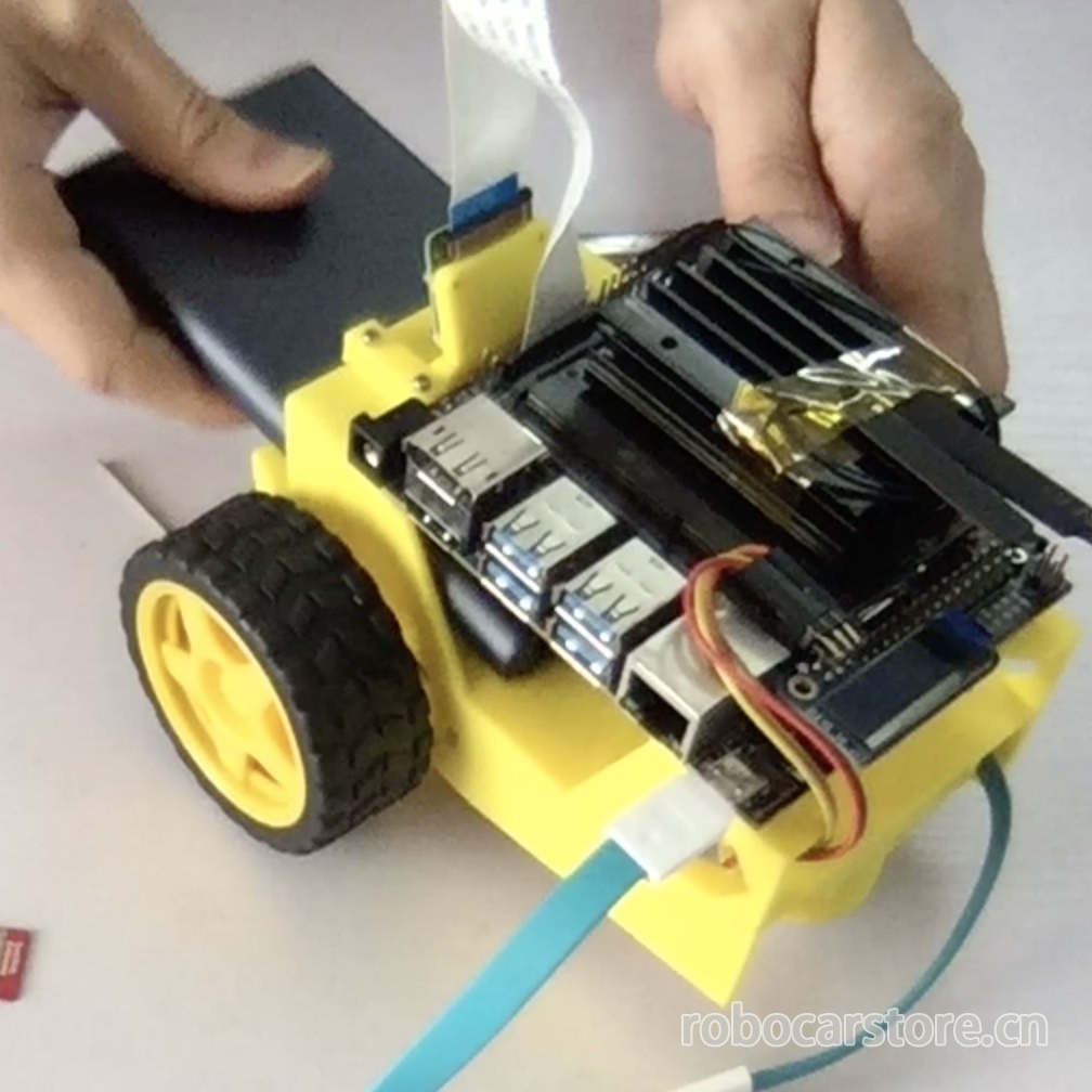
This article explains how to use jupyter lab in the browser to control your JetBot and how to program your JetBot through python.

Recognize the interface of Jupyter Lab

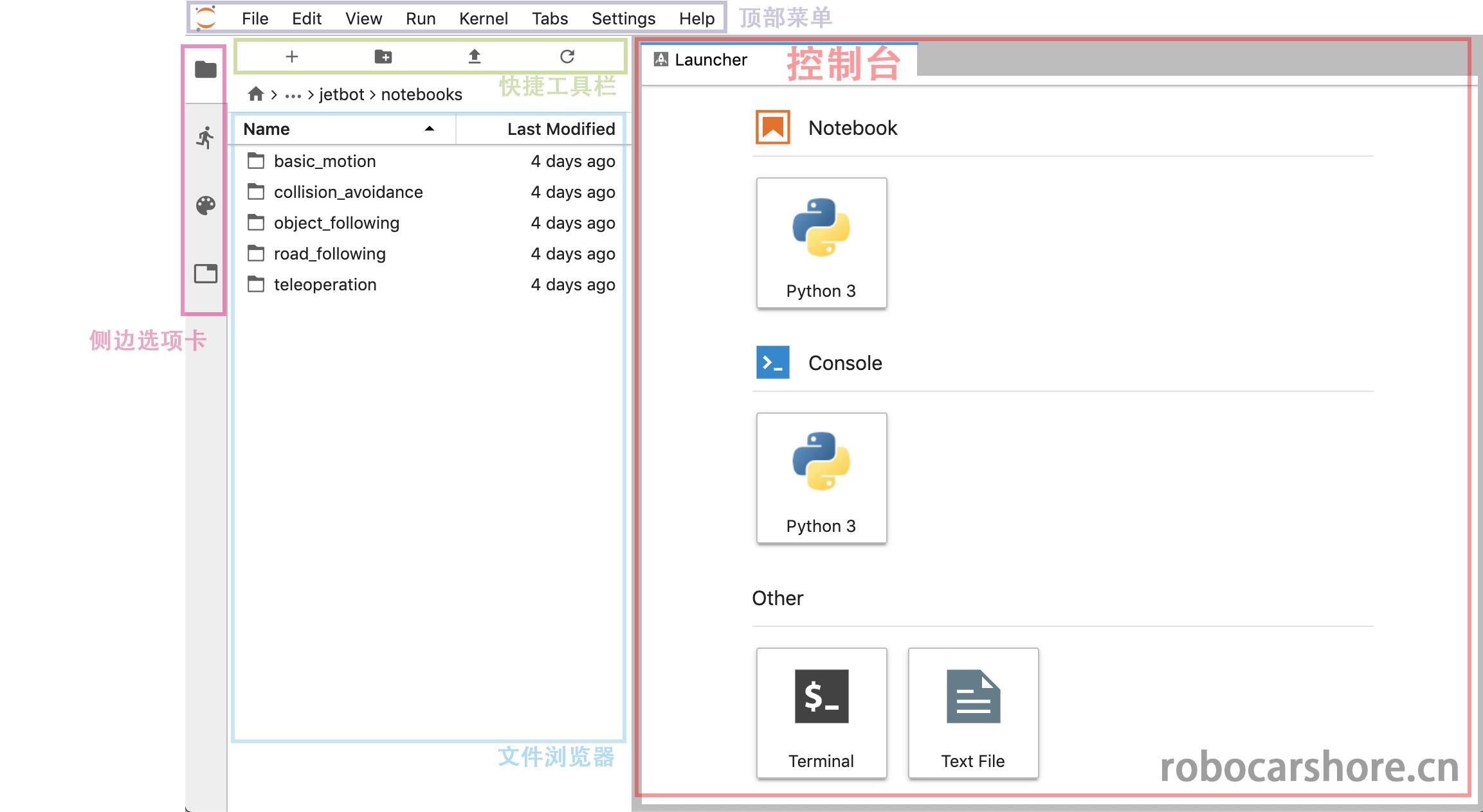
We have already used jupyter lab through the browser in the previous article, and we will continue to use this tool. Therefore, it is necessary to understand the interface of jupyter lab, and have an impression of the names of different areas, which will make your subsequent operations more convenient.

robocarstore/173808120633923478

Roughly explain:

  • Top menu:Includes all operations of jupyter lab, such as creating, saving, closing the running kernel, etc.
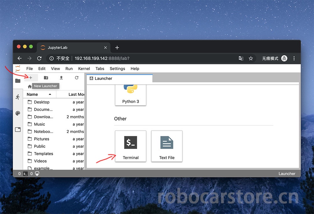
  • Console:It is a shortcut for quickly creating a notebook and opening a Terminal (terminal, or command line).
  • Quick toolbar:It is a shortcut, from left to right, which represents "create a console", "create a folder", "upload a file", "refresh".
  • Side tab:You can click on "file browser", "running kernel list", "command list", "window list" to open them.

Next, we will explain what the python statements in the notebook mean and what they are used for.

You can view the complete notebook here, with a better style:

https://github.com/ling3ye/jetbot/blob/master/notebooks/basic_motion/basic_motion.ipynb

You can also download this notebook to replace your original basic motion notebook.

Basic Movement

Welcome to the Jetbot programming interface based on jupyter lab.
This type of document is called "jupyter Notebook", which is a document that combines text, code, and graphics. It is more orderly and simple than the method of only having code and comments. If you are not familiar with 'Jupyter', I recommend you to click the "help" drop-down menu in the top menu bar, which has many usage references for Jupyter lab.

And in this notebook, we will introduce the basic programming knowledge of JetBot and how to program your JetBot through python.

Load the Robot class

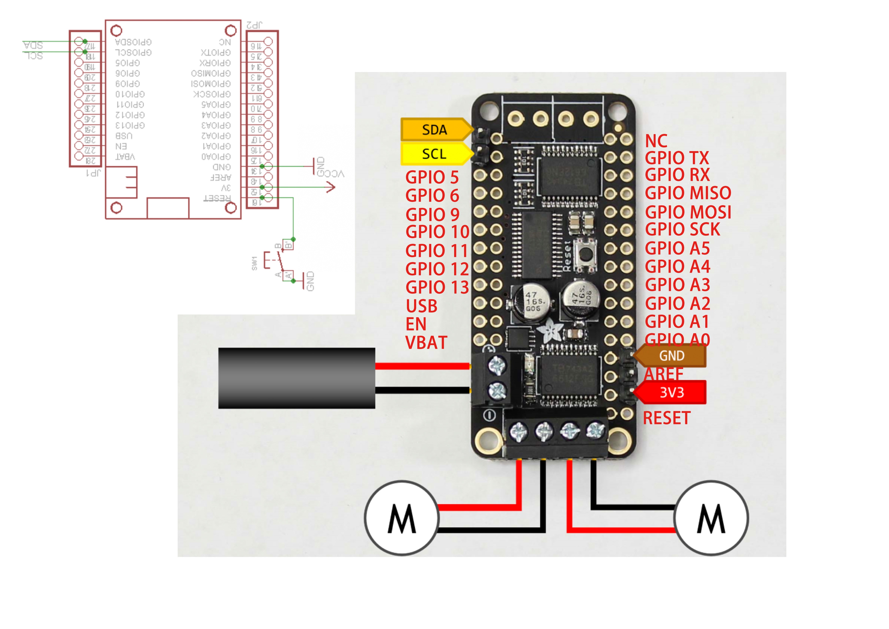
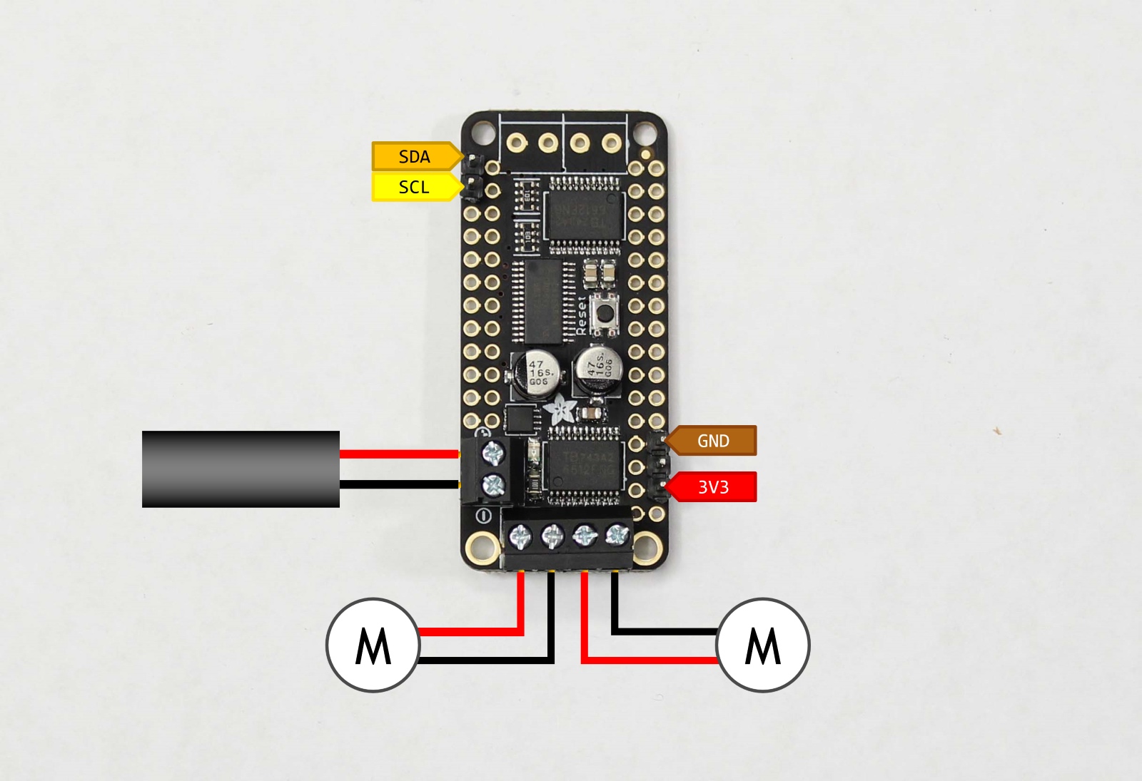
Before starting to program JetBot, we need to import the "Robot" class. This class allows us to easily control the motors of JetBot! It is included in the "jetbot" package.

If you are a Python beginner, a package is a folder containing code files.
These code files are called modules (models).

To load the Robot class, please highlight the cell below and press ctrl + enter or the play icon above. This operation will execute the code in the cell.

Now that we have loaded the Robot class, we can use the following statement to initialize this instance (instance).

Now that we have created a Robot instance named "Robot", we can use this instance to control our robot (JetBot). Execute the following command to make JetBot rotate counterclockwise at 30% of its maximum speed.

Note: This command will make the robot move. Please ensure there is enough space for the robot to move, to avoid falling and damaging the robot, or simply put it on the ground.

Great, you should now see the JetBot rotating counterclockwise!

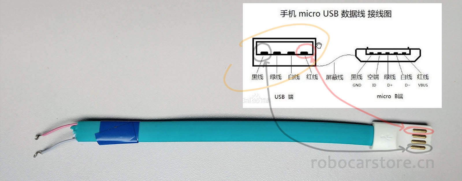
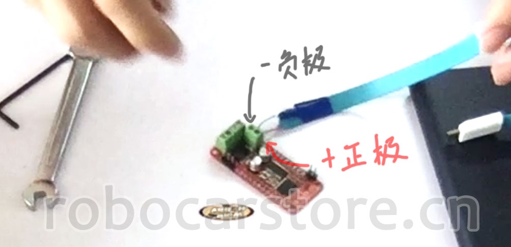
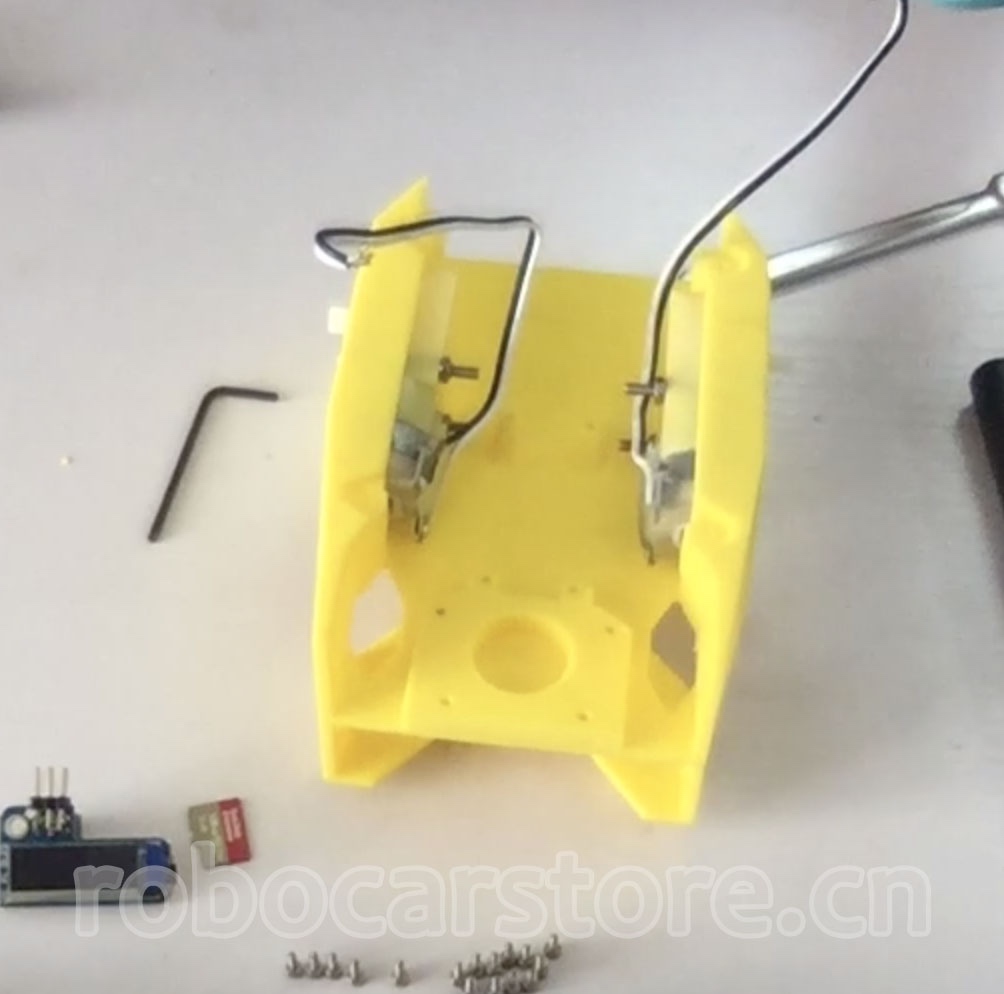
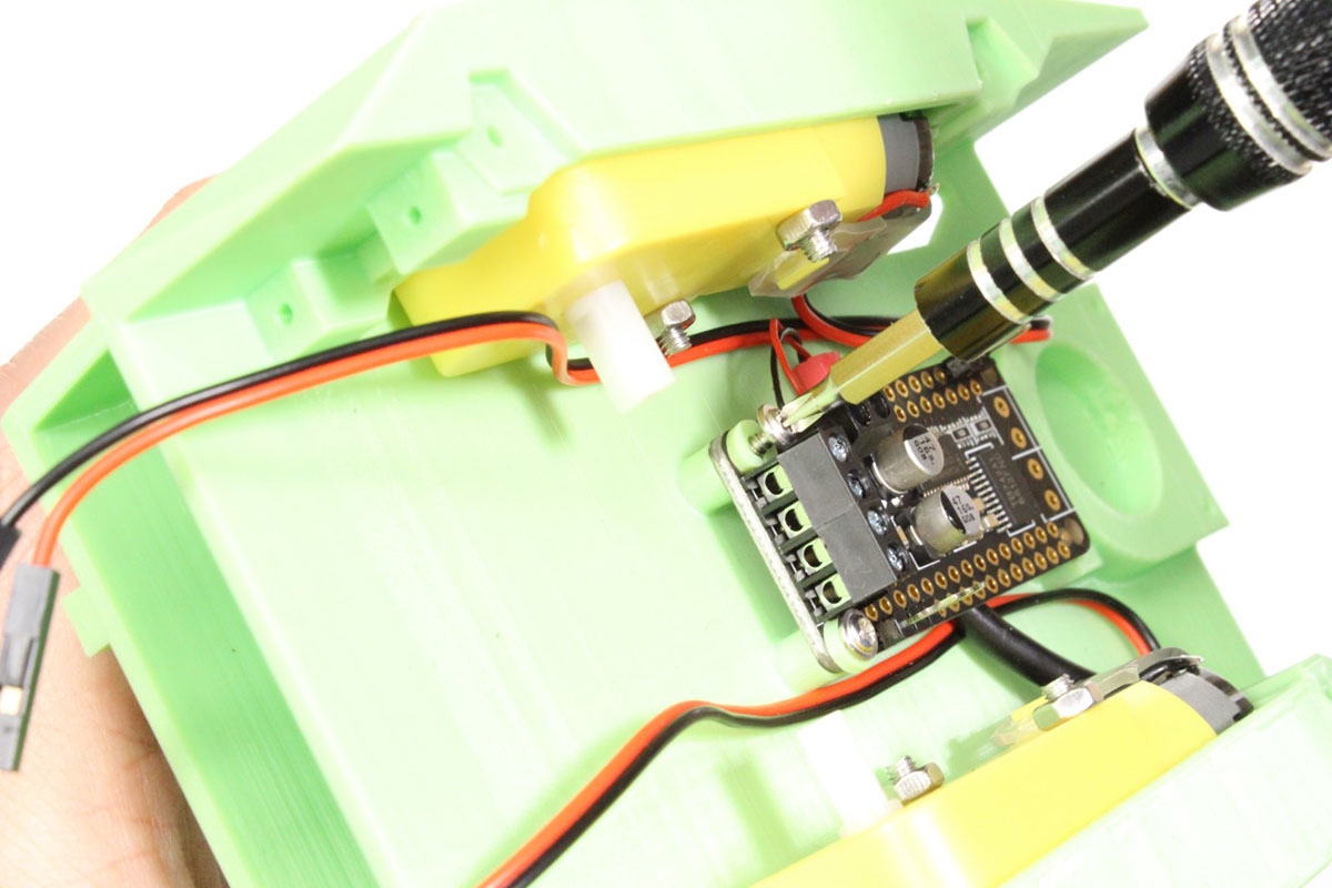
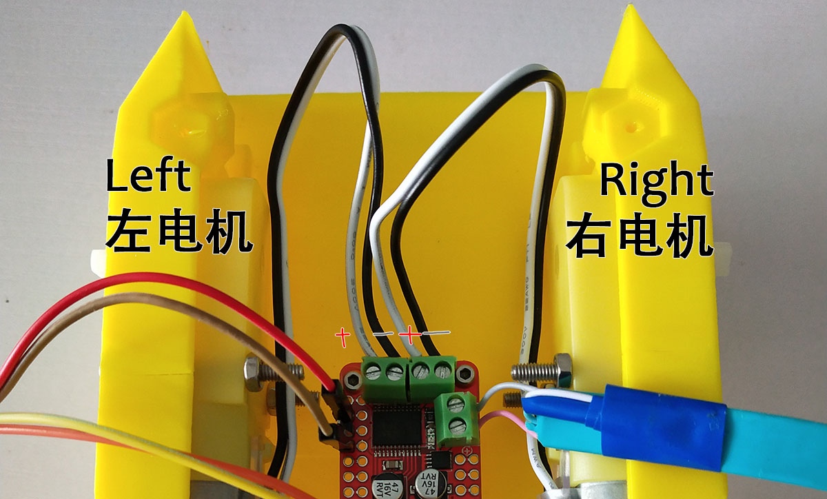
If your robot did not turn left, this means that one or both of the motors are not working properly. Try turning off the power and find the motor that is not working properly, then swap the wires of the positive and negative poles.

Reminder: Please ensure that the wires are checked carefully and the wires should be unplugged when the power is turned off.

Now, execute the following stop method to stop the robot.

Sometimes we may want to move the robot for a certain period of time. To do this, we can use the time package in Python. Execute the following code to load time.

This package defines the sleep function, which causes the code to stop for a specified number of seconds before running the next command. Try the following command combination to make the robot turn left for half a second.

Great, you should now see the JetBot left turn for a moment, then stop.

The robot class also has right, forward, and backwards methods. Try creating your own cell, refer to the previous code, and make the robot move forward at 50% speed for one second.

To create a new cell, click on the highlighted bar on the side and press "b" or click the "+" icon in the toolbar above the notebook. Once done, try to enter the code that you think will make the robot move forward at 50% speed for one second, and then execute it to verify if the code you entered is correct.

Control each motor separately

Above we saw how to use left, right etc. commands to control JetBot. But what if we want to set the speed of each motor separately? There are actually two ways to do this.

The first method is to call the set_motors method. For example, to turn left for one second, we can set the left motor speed to 30% and the right motor to 60%, which will achieve a different turning angle, as shown below.

robot.set_motors(0.3, 0.6)

Great! You should now see the JetBot turn left. But actually we can use another way to achieve the same result.

In the Robot class, there are two properties named left_motor and right_motor, which represent the speed values of the left and right motors. These properties are instances of the Motor class, each of which contains a value value. When this value changes, it triggers events, which reassign the motor speed value.

So in this motor class, we attach a function that will update the motor command whenever the value changes. Therefore, to achieve the same result as we did above, we can execute the following.

robot.left_motor.value = 0.3

robot.right_motor.value = 0.6

robot.left_motor.value = 0.0

robot.right_motor.value = 0.0

You should now see the JetBot move in the same way!

Use the traitlets library to connect to HTML controls to operate the motors

Next, we will introduce a very cool feature, which is that we can make some graphical small buttons (controls) on this page using Jupyter Notebooks, and use traitlets to connect these small widgets to control the operation. This way, we can control our car through the buttons on the web page, which will be very convenient and fun.

To illustrate how to write the program, we first create and display two sliders for controlling the motors.

import ipywidgets.widgets as widgets

from IPython.display import display

# create two sliders with range [-1.0, 1.0]

left_slider = widgets.FloatSlider(description='left', min=\-1.0, max=1.0, step=0.01, orientation='vertical')

right_slider = widgets.FloatSlider(description='right', min=\-1.0, max=1.0, step=0.01, orientation='vertical')

# create a horizontal box container to place the sliders next to eachother

slider_container = widgets.HBox([left_slider, right_slider])

# display the container in this cell's output

display(slider_container)

You should now see two vertical sliders displayed above.

Tip: In Jupyter Lab, you can actually pop out the cell to other windows, such as these two sliders. Although they are not in the same window, they are still connected to this notebook. The specific operation is to move the mouse to the cell (for example: slider) and right-click, select "Create new view for output" (Create new view for output), and then drag the window to the place you are satisfied with.

Try clicking and dragging the sliders up and down, you will see the value change. Note that the motors of the JetBot are not responding when we move the sliders, because we have not connected them to the motors yet! We will achieve this by using the link function in the traitlets package below.

left_link = traitlets.link((left_slider, 'value'), (robot.left_motor, 'value'))

right_link = traitlets.link((right_slider, 'value'), (robot.right_motor, 'value'))

Now try dragging the sliders (you need to move them slowly, otherwise your JetBot will suddenly run out of bounds and cause damage), you should see the corresponding motors turning!

We created the link function above actually creates a two-way link! This means that if we set the motor value somewhere else, the slider will update accordingly! Try executing the following code block:

Executing the above code should see the slider change, responding to the motor speed value. If we want to disconnect this connection, we can call the unlink method to disconnect each connection one by one.

But if we don't want a two-way connection, for example, we just want to use the slider to display the motor speed value, but not to control it, then to achieve this function, we can use the dlink function, the left is the source, the right is the target (the data comes from the motor, and then it is displayed on the target).

left_link = traitlets.dlink((robot.left_motor, 'value'), (left_slider, 'value'))

right_link = traitlets.dlink((robot.right_motor, 'value'), (right_slider, 'value'))

Now you can move the sliders up and down, you should see that the robot's motors have no reaction. But when we set the motor speed value and execute it, the slider will respond to the corresponding numerical update.

Add functions to events

Another way to use traitlets is to attach functions to events (for example forward). As soon as the object changes, the function will be called, and some information about the change will be passed, such as the old value and the new value.

Let's create some buttons to control the robot displayed in the notebook.

button_layout = widgets.Layout(width='100px', height='80px', align_self='center')

stop_button = widgets.Button(description='stop', button_style='danger', layout=button_layout)

forward_button = widgets.Button(description='forward',

backward_button = widgets.Button(description='backward', layout=button_layout)

left_button = widgets.Button(description='left', layout=button_layout)

right_button = widgets.Button(description='right', layout=button_layout)

middle_box = widgets.HBox([left_button, stop_button, right_button],

layout=widgets.Layout(align_self='center'))

controls_box = widgets.VBox([forward_button, middle_box, backward_button])

You should now see a set of robot control buttons displayed above, but clicking the buttons will not do anything. To control, we need to create some functions attached to the on_click event of the buttons.

def step_forward(change):

def step_backward(change):

Now that we have defined those functions, let's attach them to the on_click event of each button.

# link buttons to actions

stop_button.on_click(stop)

forward_button.on_click(step_forward) backward_button.on_click(step_backward) left_button.on_click(step_left)

right_button.on_click(step_right)

Now, when you click each button, you should see the JetBot move accordingly.

Heartbeat switch

Here we show how to use the 'heartbeat' package to stop the movement of the JetBot. This is a simple way to detect if the JetBot is still connected to the browser. You can adjust the heartbeat period (in seconds) using the slider shown below. If the heartbeat cannot communicate back and forth between the browser, the heartbeat's status property will be set to dead. Once the connection is restored, the status property will be set to alive.

from jetbot import Heartbeat

# this function will be called when heartbeat 'alive' status changes

def handle_heartbeat_status(change):

if change['new'] == Heartbeat.Status.dead:

heartbeat.observe(handle_heartbeat_status, names='status')

period_slider = widgets.FloatSlider(description='period', min=0.001, max=0.5, step=0.01, value=0.5)

traitlets.dlink((period_slider, 'value'), (heartbeat, 'period'))

display(period_slider, heartbeat.pulseout)

Try executing the following code to start the motor, then lower the slider to see what happens. You can also try turning off your robot or computer.

Summary

This is a simple notebook example, I hope it will help you build confidence in programming your JetBot.

给大家介绍一下!Donkey Car

Donkey Car

Donkey Car,是一款开源的小型DIY自驾平台,这可能是你最佳的AI入门学习平台。Donkey是用Python写的高级自动驾驶库,它的特点是让你可以快速学习机器学习,快速实验,综合应用机器视觉,机器学习工具(例如:tornado, keras, tensorflow, opencv, ….)

什么是Donkey Car?

Donkey Car是一个基于Python的开源项目,旨在帮助用户构建和训练自动驾驶汽车。它的设计初衷是让用户能够在家中或实验室中轻松地进行自动驾驶技术的实验。Donkey Car的硬件部分通常由一个小型遥控车、Raspberry Pi、摄像头和电池组成。软件部分则是一个强大的Python库,支持多种机器学习框架。

为什么选择Donkey Car?

  1. 易于上手:Donkey Car的设计非常直观,即使是没有编程经验的人也可以快速上手。它提供了详细的文档和教程,帮助用户一步步完成从硬件组装到软件配置的全过程。

  2. 社区支持:作为一个开源项目,Donkey Car拥有一个活跃的社区。无论你遇到什么问题,都可以在社区中找到答案或寻求帮助。

  3. 灵活性:Donkey Car支持多种机器学习框架,如TensorFlow和Keras,用户可以根据自己的需求选择合适的工具进行实验。

  4. 成本低廉:相比于其他自动驾驶平台,Donkey Car的成本相对较低,非常适合个人爱好者和教育机构使用。

如何开始?

要开始使用Donkey Car,你需要准备以下材料:

  • 一辆小型遥控车
  • Raspberry Pi
  • 摄像头
  • 电池
  • 3D打印的车架(可选)

接下来,你可以按照官方文档的指导进行硬件组装和软件安装。Donkey Car的官方GitHub页面提供了详细的安装步骤和示例代码,帮助你快速搭建自己的自动驾驶汽车。

结论

Donkey Car是一个非常适合AI初学者的项目。通过这个平台,你可以学习到自动驾驶的基本原理,掌握机器学习和计算机视觉的基础知识。无论你是想要进入AI领域,还是只是对自动驾驶技术感兴趣,Donkey Car都将是一个理想的起点。

希望这篇文章能帮助你更好地了解Donkey Car,并激发你对自动驾驶技术的兴趣。快来加入Donkey Car社区,开始你的AI学习之旅吧!

Donkey Car详解(1) – 组装

Donkey Car

概述

Donkey Car是2016年10月由美国人Adam Conway(Twitter)主导的一个人工智能自动驾驶模型车项目,由于近几年来人工智能技术和自动驾驶技术逐渐兴起,这个自动驾驶项目也受到越来越多爱好者关注和加入,逐渐形成了DonkeyCar社群。

本教程目标是帮助DonkeyCar初学者快速上手,如果有问题或建议,欢迎拍砖。

选择车架

最初的Donkey Car是通过改装“Exceed”牌1/16四驱玩具车而成,官方文档推荐一下四个型号:

以上四款小车的电子驱动模块都是一样的,它们但区别在于轮胎和安装顶盖的方式。需要提醒的是Desert Monster,Short Course Truck和Blaze需要增加一个适配器来固定Donkey Car主板和把手,可以在玩具店购买或者自己打印。因为这些小车都是标准配置,基本上是即插即用的。这些小车都有有刷电机版本和无刷电机版本,作者说使用有刷电机版的车架更容易训练,因为有刷电机更适合在粗糙的路面驾驶,也更便宜。

后来玩具们开始改装1/10的玩具车,1/10的车子变得更大,升级成Doneky Car专业版。当然专业版的Donkey Car性能更好,价格也更贵,以下是支持的型号:

  • HobbyKing Trooper (非专业版) 链接
  • HobbyKing Mission-D 链接
  • Tamaya TT01或者它的山寨版,这款容易购买,但需要散件安装,有一定难度。

因为完专业版的DonkeyCar的人比普通版的少,因为专业版存在文档不足的问题,如果你要开始完Donkey Car Pro,你应该具备一定的动手能力和更多的耐性。

所需零件

根据不同主板的支持,Donkey Car有两个版本,一款是使用树莓派(Raspberry Pi)的Donkey Car,另一款是使用Jetson Nano的Donkey Car。两个版本除了主板不同,所需的配件和软件的安装也是不一样的。

选项1 – 你可以通过Donkey Car官方渠道购买

如果你在美国,可以到原作者的Donkey store商店购买。

如果你在亚洲,你可以选择香港的Robocar Store,或者中国大陆的Robocar Store China购买。

官方套件或整车包括

零件大约成本
车架(来自上面的玩具车)大约¥600
电池及充电器大约¥120
树莓派 3b+大约¥300
128G SD卡大约¥120
其他配件大约¥600 – ¥875

选项2 – 你可以通过零件清单购买

如果你需要自己购买零部件,你可以参考作者的链接。值得提醒的是,如果你要自己组装,是需要通过3D打印机打印Donkey Car的零部件。如果你没有3D打印机,可以到红菜3D选购一台。

具体要准备的打印零部件,可以参考官方文档,

Jetson Nano升级

如果你想你小车跑得更快,你可以选择具有GPU的Jetson Nano作为主板,除了需要换主板意外,你还需要另外准备一个Jetson Nano的主板适配器还有Jetson Nano的网卡和Jetson Nano适用的摄像头(可参考这篇文章)

JetsonNano适配器

Jetson Nano 适配器

JesonNano扩展板

注意Jetson Nano的pin口布局和树莓派相反,使用其他扩展板时要注意。

电池

我们强烈建议使用聚合物锂电池,因为聚合物锂电池的能量密度更高,而且电压下降曲线更平滑,因而电压更稳定。

Battery

硬件

如果你从官方商店购买Donkey Car,你可以跳过前两步。

第一步 打印零部件

如果你没有3D打印机,可以在我们的商店购买打印好的零部件,或者寻找第三方打印。如果使用 PLA打印,层高设置可以选择2mm,填充率30%,打印一套零部件,估计需要2天时间左右,这是模型的下载链接

第二步 清理零部件

所有的3D打印件都需要做一点清理,包括重新钻孔,清理拉丝等。

robocarstore/17380757722502808

robocarstore/17380757862515729

第三步 安装底板和手提支架

安装步骤是相当简单的,你只需要使用M3螺丝把底板和手提把手连接起来。你要确保螺丝上紧了,因为你会使用手提支架提起小车。

第四步 连接舵机控制器

你可以把电路板安装上底板上再做连线,连线入下图所示。

robocarstore/173807580225062010

robocarstore/173807581725157711

这是树莓派的布局图,你需要连接3.3v、两个I2C pin (SDA和SCL) 和 Ground(接地)

第五步 将树莓派安装到底板上

在这个时候,你可以把已经烧录好的SD卡插入树莓派卡槽。然后把树莓派和舵机连通过螺丝安装到底板上。这时需要使用M2.6的螺丝。

(加图片)

第六步 安装摄像头

先把摄像头的数据线连接好,然后安装到手提支架到前方,如下图:

注意树莓派到安装方向,如果摄像头前有薄膜保护,记得要把保护膜撕掉以免影响训练效果。

第七步 安装到车架上

使用R型扣把底板固定在车架上,然后连接上电源线。

robocarstore/173807583625096212

恭喜你,你的小车安装完成!

要驱动你的小车,你就需要继续参考下一篇文章软件安装部分

Introducing Donkey Car!

Donkey Car

Donkey Car is an open-source, small-scale DIY autonomous driving platform, and it might be your best entry-level AI learning platform. Donkey is a high-level autonomous driving library written in Python, characterized by its ability to help you quickly learn machine learning, experiment rapidly, and integrate applications of computer vision and machine learning tools (such as tornado, keras, tensorflow, opencv, etc.).

What is Donkey Car?

Donkey Car is a Python-based open-source project designed to help users build and train autonomous vehicles. It is intended to allow users to easily experiment with autonomous driving technology at home or in a lab. The hardware part of Donkey Car typically consists of a small remote-controlled car, a Raspberry Pi, a camera, and a battery. The software part is a powerful Python library that supports multiple machine learning frameworks.

Why Choose Donkey Car?

  1. Easy to Get Started: Donkey Car is designed to be very intuitive, allowing even those without programming experience to get started quickly. It provides detailed documentation and tutorials to guide users through the entire process from hardware assembly to software configuration.

  2. Community Support: As an open-source project, Donkey Car has an active community. Whatever issues you encounter, you can find answers or seek help within the community.

  3. Flexibility: Donkey Car supports multiple machine learning frameworks, such as TensorFlow and Keras, allowing users to choose the right tools for their experiments based on their needs.

  4. Cost-Effective: Compared to other autonomous driving platforms, Donkey Car is relatively low-cost, making it ideal for hobbyists and educational institutions.

How to Get Started?

To start using Donkey Car, you need to prepare the following materials:

  • A small remote-controlled car
  • Raspberry Pi
  • Camera
  • Battery
  • 3D printed car frame (optional)

Next, you can follow the official documentation to assemble the hardware and install the software. Donkey Car's official GitHub page provides detailed installation steps and example code to help you quickly build your own autonomous vehicle.

Conclusion

Donkey Car is a project well-suited for AI beginners. Through this platform, you can learn the basic principles of autonomous driving and master the fundamentals of machine learning and computer vision. Whether you want to enter the AI field or are simply interested in autonomous driving technology, Donkey Car is an ideal starting point.

I hope this article helps you better understand Donkey Car and inspires your interest in autonomous driving technology. Join the Donkey Car community and start your AI learning journey today!

Donkey Car Detailed Explanation (1) – Assembly

Donkey Car

Overview

Donkey Car is an AI autonomous driving model car project led by Adam Conway (Twitter) since October 2016. With the rise of AI and autonomous driving technologies in recent years, this project has attracted more enthusiasts, forming the DonkeyCar community.

This tutorial aims to help DonkeyCar beginners get started quickly. If you have any questions or suggestions, feel free to provide feedback.

Choosing a Chassis

The original Donkey Car was modified from the "Exceed" brand 1/16 four-wheel-drive toy car. The official documentation recommends the following models:

These cars have the same electronic drive modules, differing only in tires and body mounting methods. Note that the Desert Monster, Short Course Truck, and Blaze require an adapter to secure the Donkey Car motherboard and handle, which can be purchased or 3D printed. These cars are standard configurations, mostly plug-and-play. They come in brushed and brushless motor versions; the author suggests using the brushed motor version as it's easier to train, better for rough surfaces, and cheaper.

Later, enthusiasts began modifying 1/10 scale toy cars, making them larger and upgrading to the Donkey Car Pro version. The Pro version offers better performance but at a higher cost. Supported models include:

  • HobbyKing Trooper (non-Pro) Link
  • HobbyKing Mission-D Link
  • Tamaya TT01 or its clones, which are easy to buy but require assembly, posing some difficulty.

Fewer people use the Pro version due to documentation gaps, so if you start with Donkey Car Pro, you should have good hands-on skills and patience.

Required Parts

Donkey Car has two versions based on the mainboard: one using Raspberry Pi and the other using Jetson Nano. Apart from the mainboard, the required parts and software installation differ.

Option 1 – Purchase through Donkey Car official channels

If you're in the US, you can buy from the original author's Donkey store.

In Asia, you can choose Hong Kong's Robocar Store or mainland China's Robocar Store China.

Official kits or complete cars include:

PartApproximate Cost
Chassis (from the toy cars above)Approx. ¥600
Battery and ChargerApprox. ¥120
Raspberry Pi 3b+Approx. ¥300
128G SD CardApprox. ¥120
Other AccessoriesApprox. ¥600 – ¥875

Option 2 – Purchase parts individually

If you need to buy parts individually, refer to the author's links. Note that if you assemble it yourself, you'll need to 3D print Donkey Car parts. If you don't have a 3D printer, consider buying one from Beets3D.

For specific printed parts, refer to the official documentation, link.

Jetson Nano Upgrade

For faster performance, choose Jetson Nano with a GPU as the mainboard. Besides changing the mainboard, you'll need a Jetson Nano adapter, network card, and compatible camera (see this article).

JetsonNano Adapter

Jetson Nano Adapter

JetsonNano Expansion Board

Note that Jetson Nano's pin layout is opposite to Raspberry Pi's, so be careful when using other expansion boards.

Battery

We strongly recommend using lithium polymer batteries for their higher energy density and smoother voltage drop curve, providing more stable voltage.

Battery

Hardware

If you purchased Donkey Car from the official store, you can skip the first two steps.

Step 1: Print Parts

If you don't have a 3D printer, buy printed parts from our store or find a third-party printer. For PLA printing, set layer height to 2mm and infill to 30%. Printing a set of parts takes about 2 days. Here's the model download link.

Step 2: Clean Parts

All 3D printed parts need some cleaning, including re-drilling holes and removing strings.

robocarstore/17380757722502808

robocarstore/17380757862515729

Step 3: Install Baseplate and Handle

The installation is straightforward; use M3 screws to connect the baseplate and handle. Ensure the screws are tight, as you'll use the handle to lift the car.

Step 4: Connect Servo Controller

Install the circuit board on the baseplate before wiring, as shown below.

robocarstore/173807580225062010

robocarstore/173807581725157711

This is the Raspberry Pi layout. Connect 3.3v, two I2C pins (SDA and SCL), and Ground.

Step 5: Install Raspberry Pi on Baseplate

At this point, insert the pre-burned SD card into the Raspberry Pi slot. Then, mount the Raspberry Pi and servo controller on the baseplate using screws. Use M2.6 screws.

(Add image)

Step 6: Install Camera

Connect the camera cable, then mount it on the front of the handle, as shown:

Ensure the Raspberry Pi is installed correctly. If the camera has a protective film, remove it to avoid affecting training results.

Step 7: Mount on Chassis

Use R-clips to secure the baseplate to the chassis, then connect the power cable.

robocarstore/173807583625096212

Congratulations, your car is assembled!

To drive your car, continue with the next article on software installation.