Play with JetBot Autonomous Driving (2) Assemble Jetbot Car
This article will detail the hardware installation process of JetBot, and provide a full installation video.
Due to the main camera malfunction during filming, the video content is unavailable, so only the material from the secondary camera is used, and the quality is somewhat unsatisfactory. Please forgive me.
You can also refer to the installation process of the official Git to complement the shortcomings (some pictures in this article are also from here):
https://github.com/NVIDIA-AI-IOT/jetbot/wiki/hardware-setup
Required Tools
M3 wrench, M2 wrench, M3 hex nut wrench, cross screwdriver, flat screwdriver, insulating tape, high temperature tape, 3M double-sided tape, soldering iron (some parts need to be soldered).
Start Assembling
Step – 1 Install Wireless Network Card
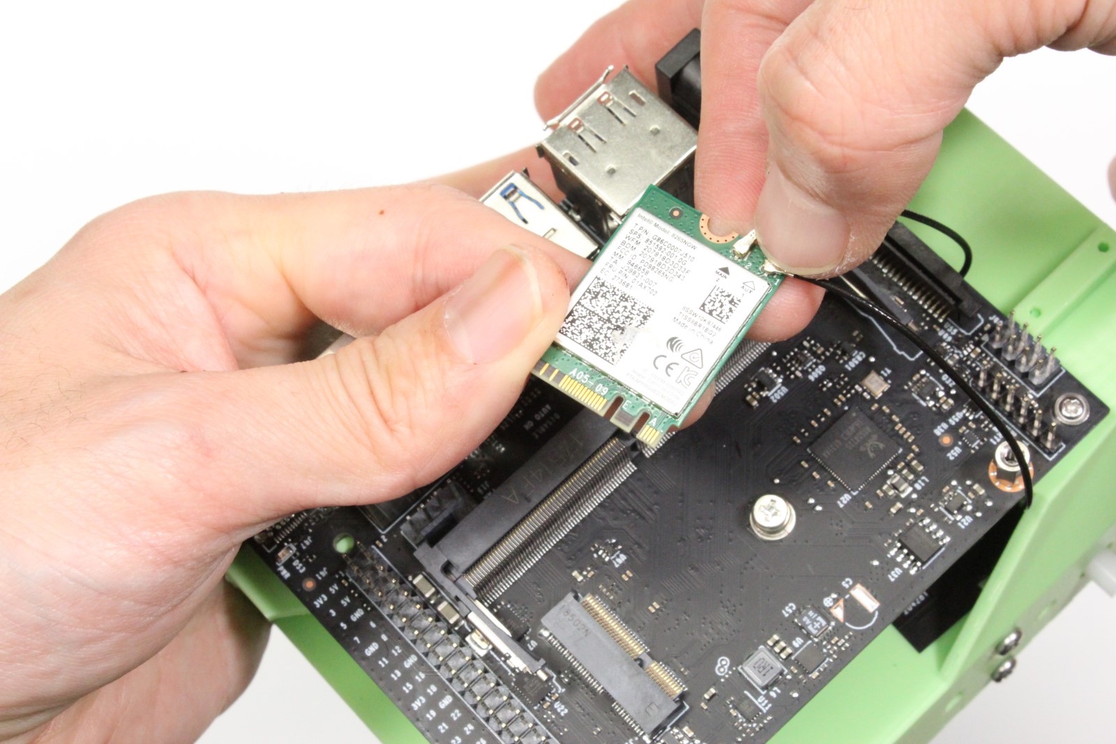
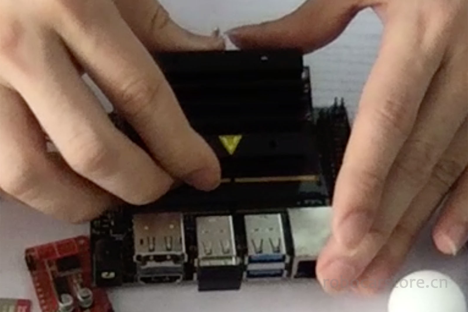
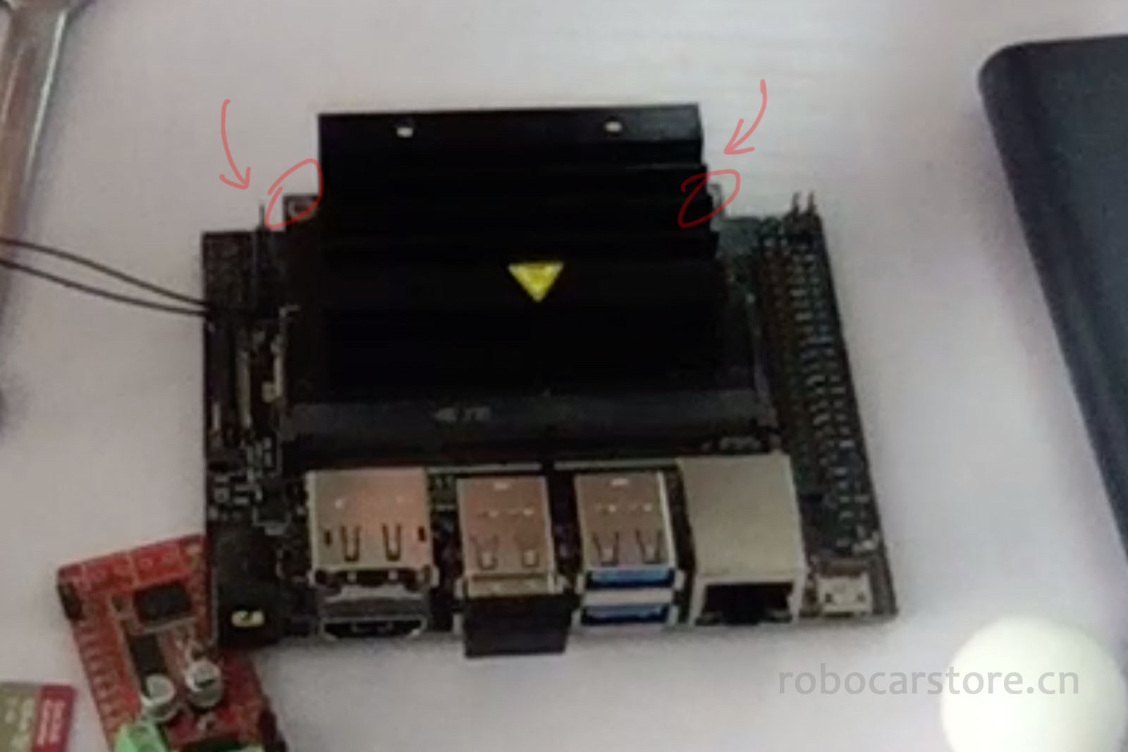
1,Remove the chip module (the entire module with the heatsink) from the Jetson Nano
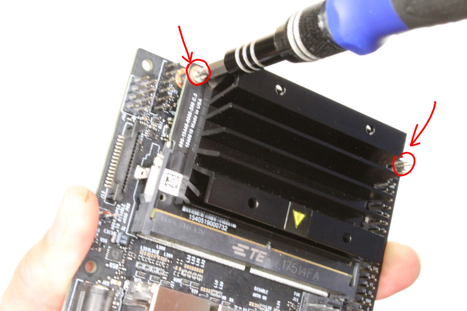
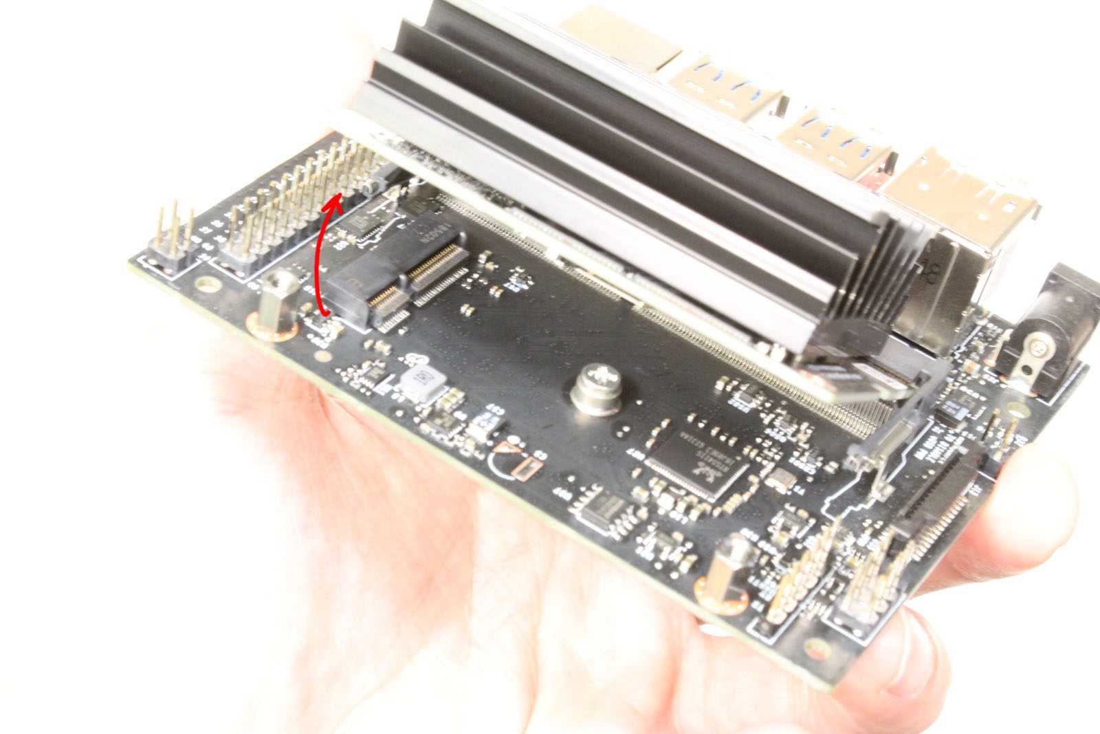
First, unscrew the 2 screws, then pull the side lock (侧锁) apart, the chip module will automatically pop up at an angle, slide the chip module out along this angle.

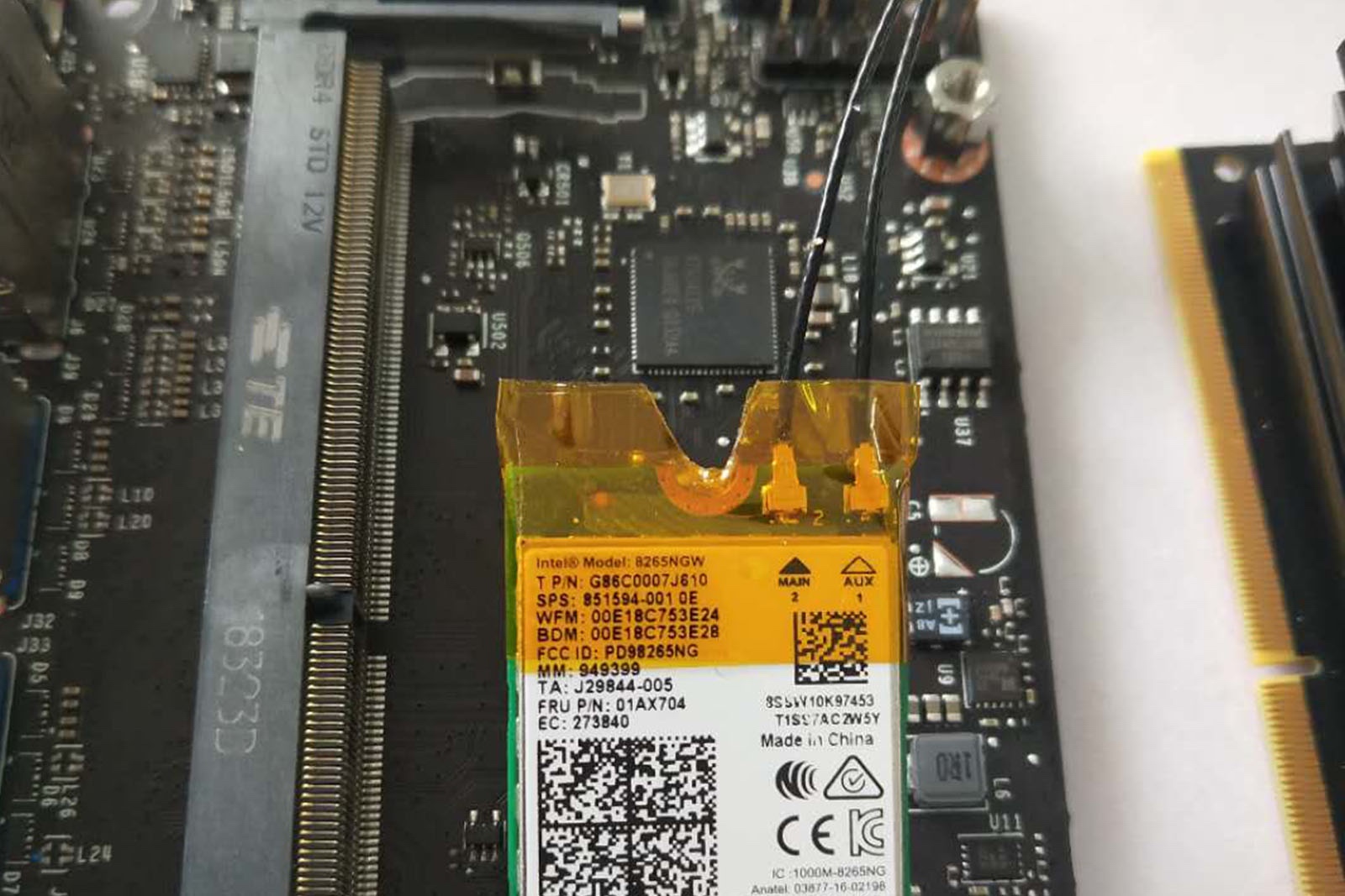
2,Install WiFi Module AC8265
Connect the Intel WiFi module AC8265 to the antenna, wrap it with high temperature tape to reinforce it, avoid falling off, and cut the high temperature tape on the groove. Screw the screws of the Jetson Nano base, plug the WiFi module into the WiFi slot, and screw the screws back in to fix the AC8265 WiFi module.
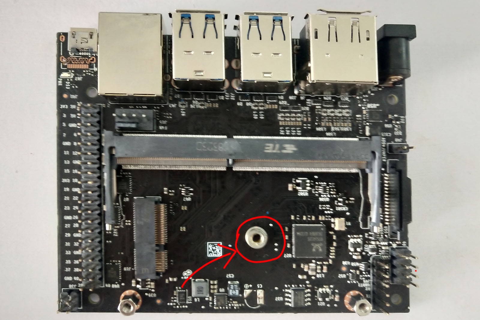
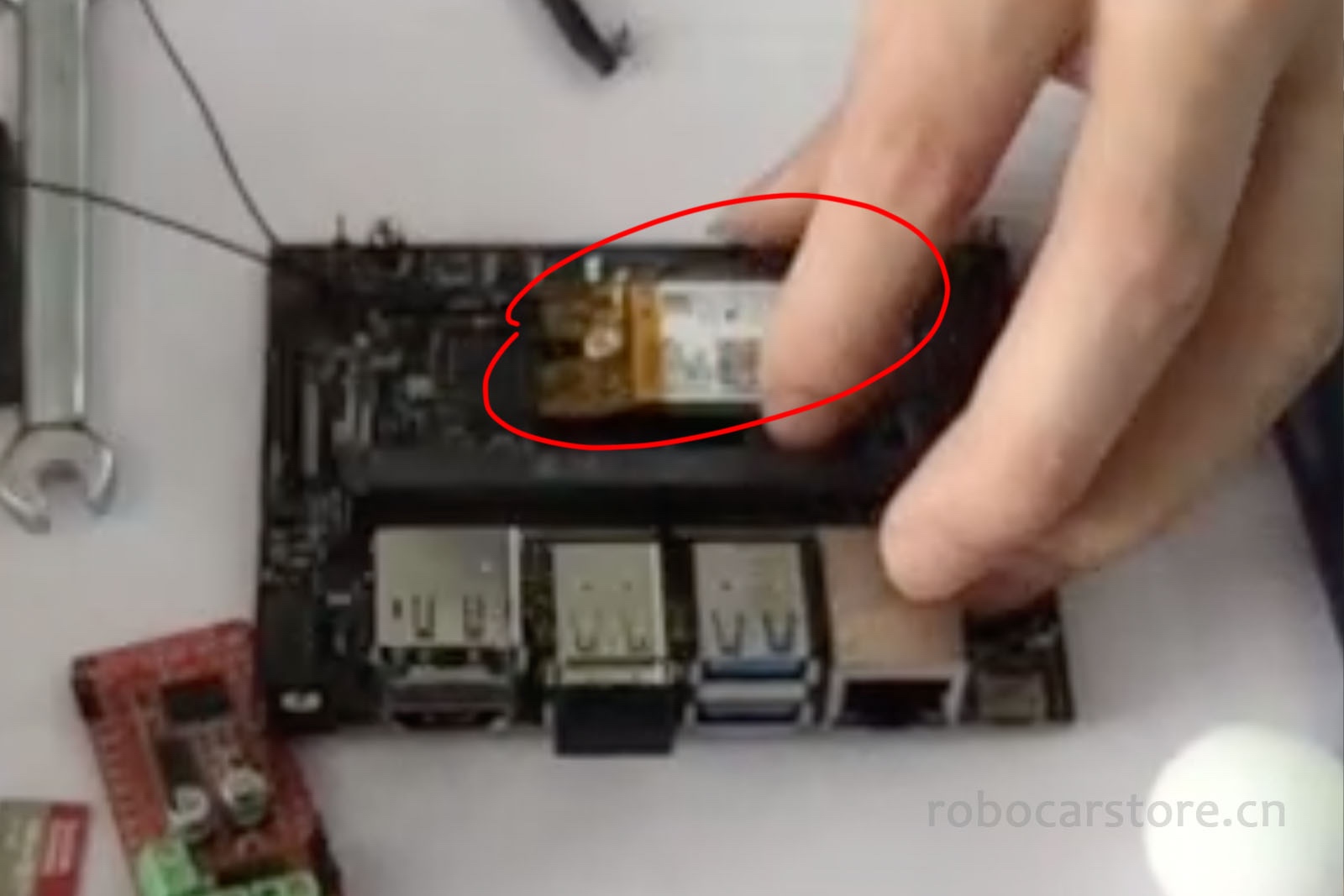
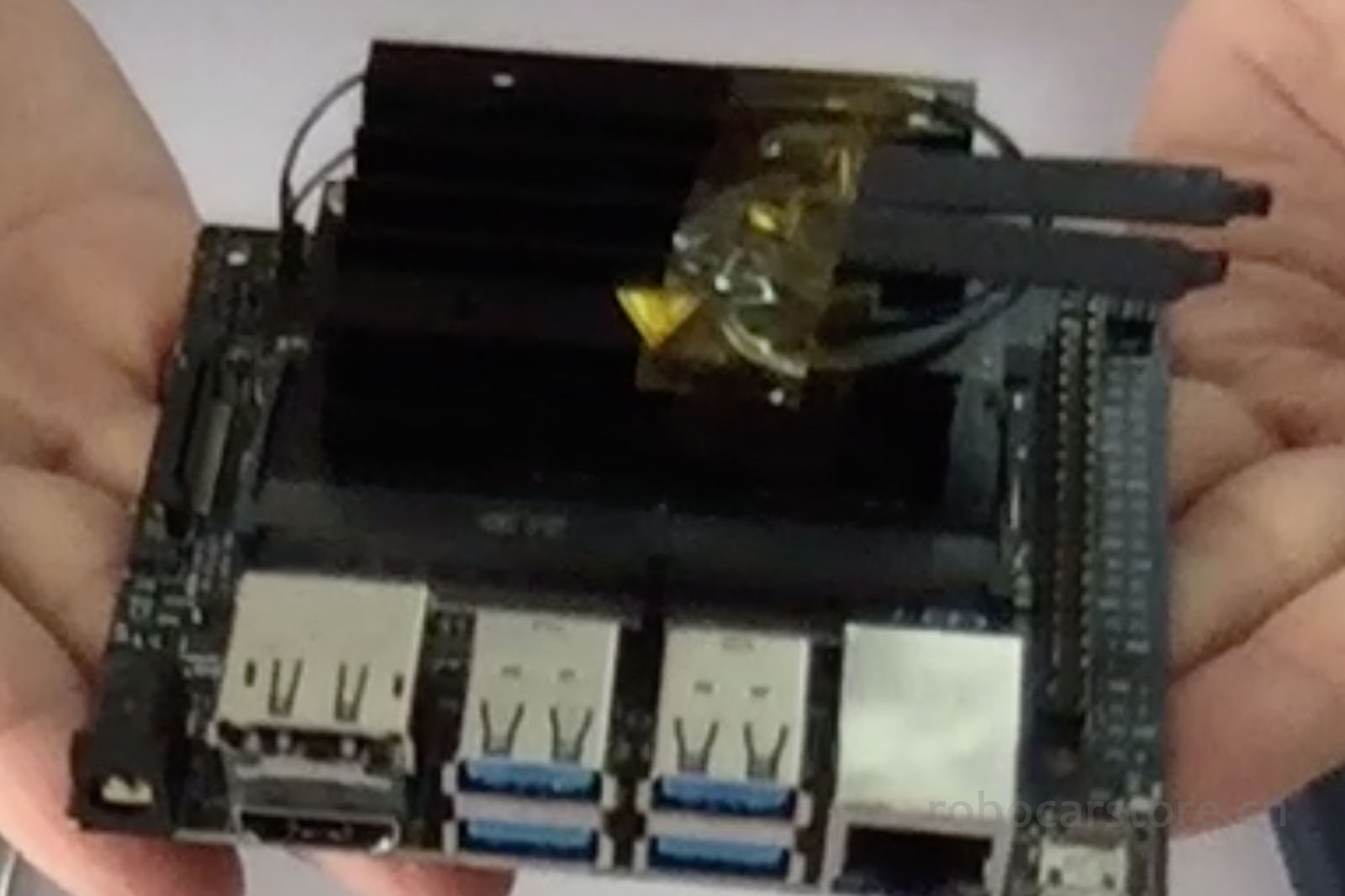
3,Install the chip module back to the Jetson Nano base, and fix the antenna
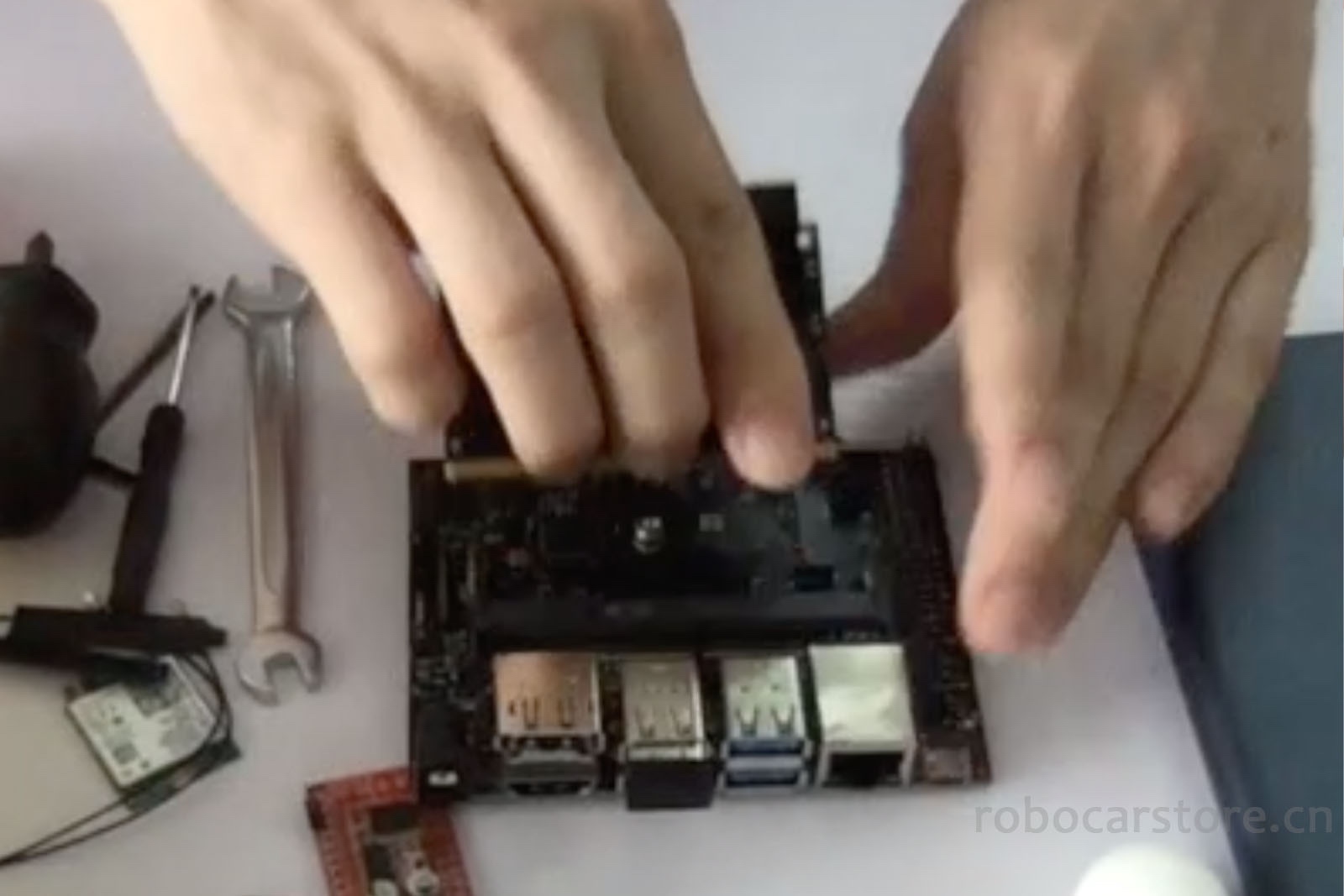
Plug the chip module back into the slot, press flat, the side lock (侧锁) will automatically snap back in place, screw the 2 screws back in to fix the chip module, and then use high temperature tape to fix the antenna to the heatsink.
Step – 2 Connect Power Line to Motor Driver
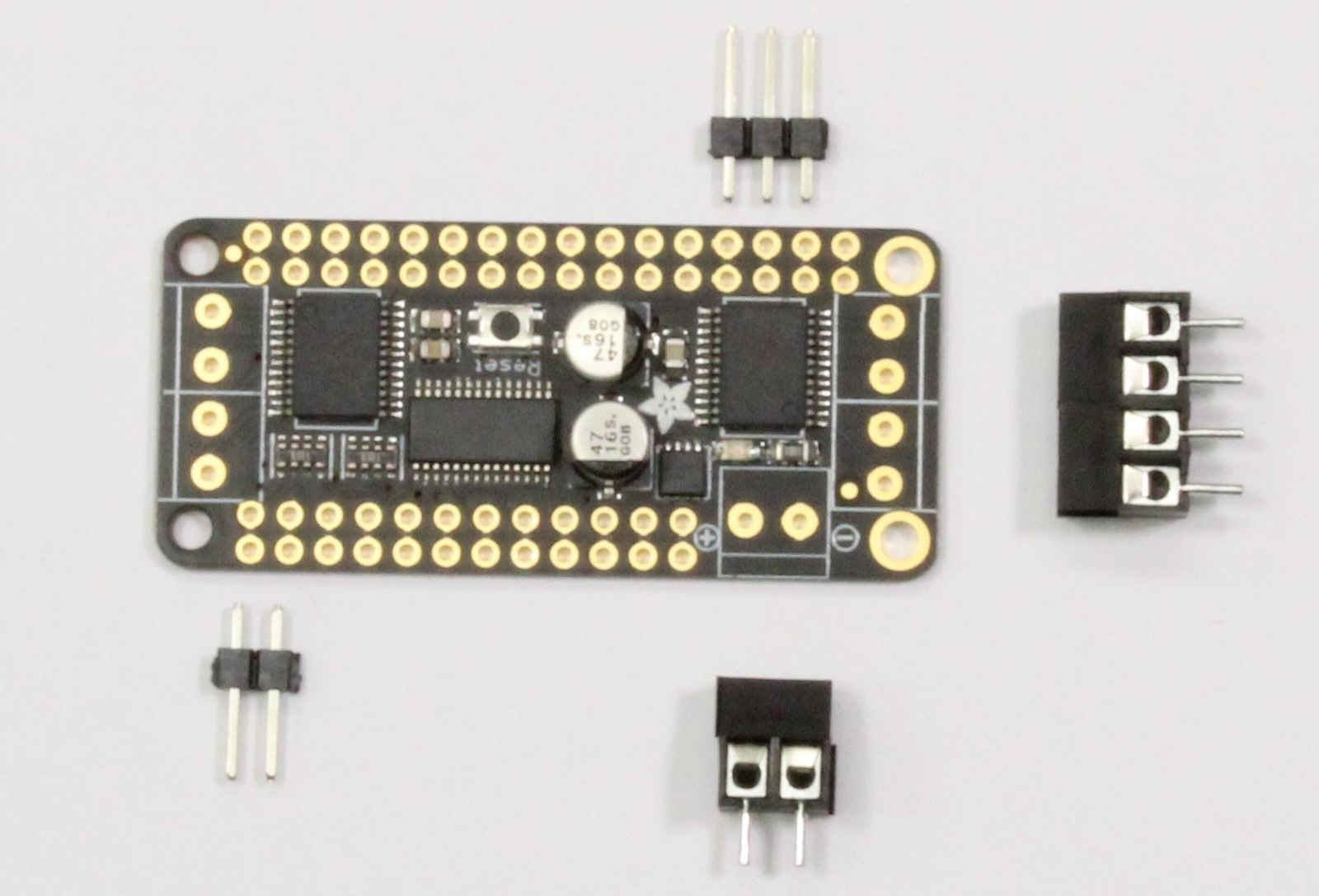
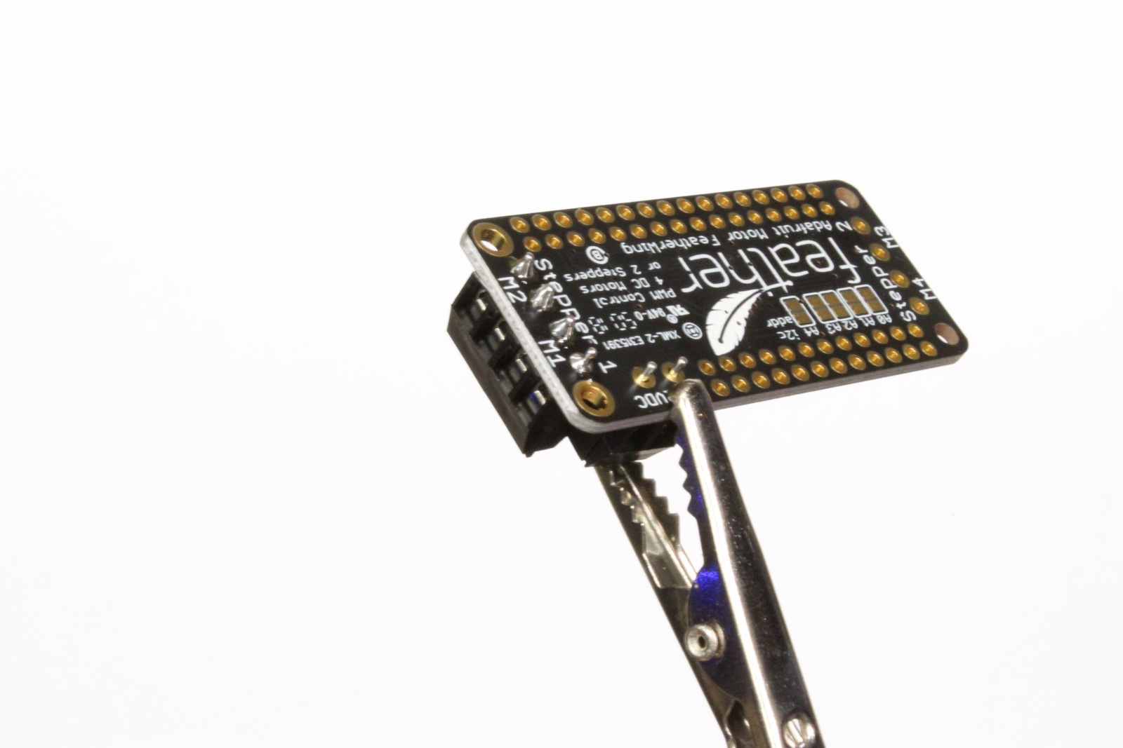
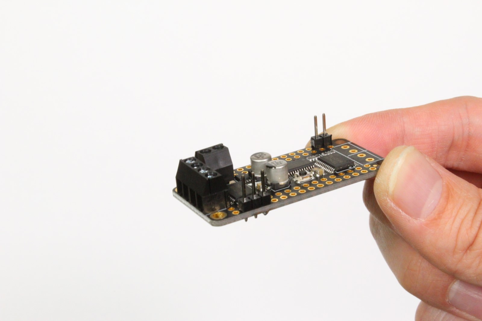
4,Solder the Motor Driver Module
Here you need to solder, when you buy this motor driver module, some accessories will be included, you only need to solder the interface shown in Figure 1, and the final processing is shown in Figure 4.

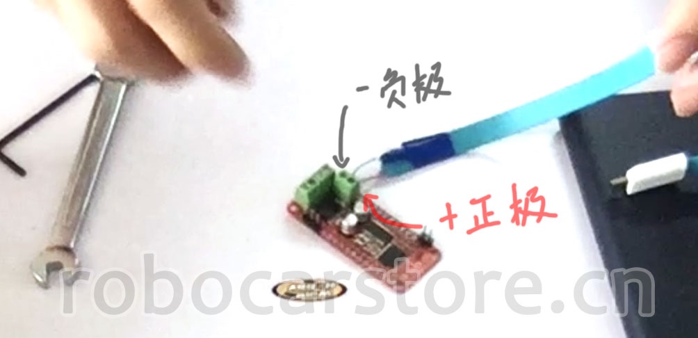
5,Unwrap the Positive and Negative Poles of the MicroUSB Power Line
As shown below, peel off the positive and negative wires, and fix the other wires with insulating tape to prevent short circuits. Generally, it is red positive and black negative, if you are not sure, please refer to the MicroUSB data line connection diagram in the picture, use a multimeter to measure. You can also connect an LED light, use the characteristics of the diode, and turn on the power to test whether the positive and negative poles are correct.
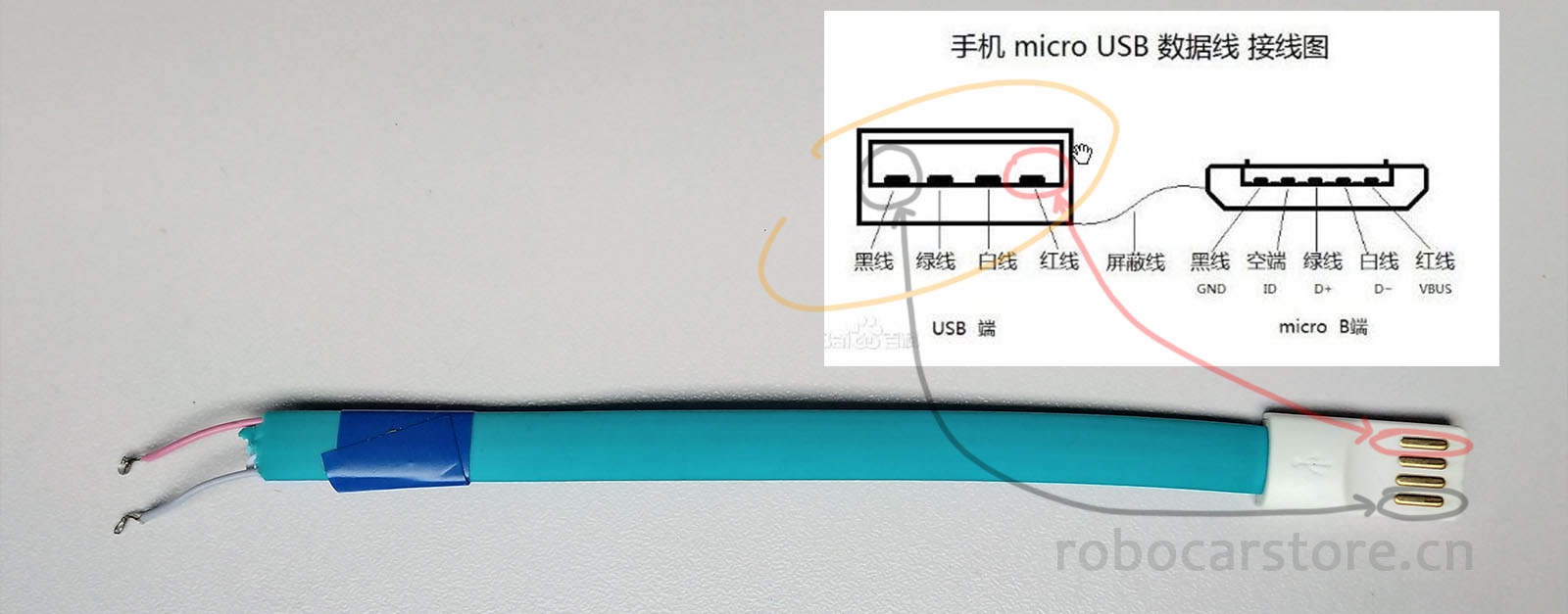
Note: The positive and negative poles must be clearly identified, if you get it wrong, it may burn your Jetson Nano, or even cause a power explosion.
Make sure to get it right!
Make sure to get it right!
Make sure to get it right!
Important things are said three times! If you have no experience, you must ask someone with experience for help!
6,Motor Driver Module Power Interface Connection to MicroUSB Data Line
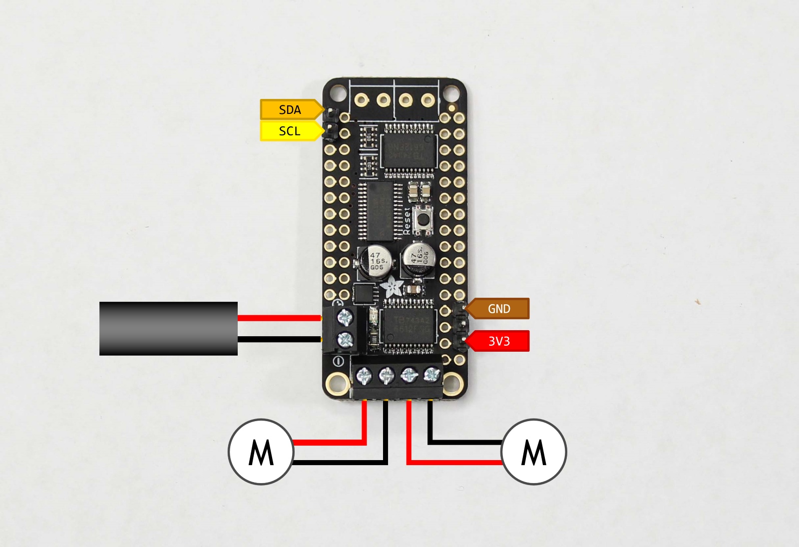
First, look at the interface of this motor driver module, it is actually an integrated board of PCA9685 and TB6612.
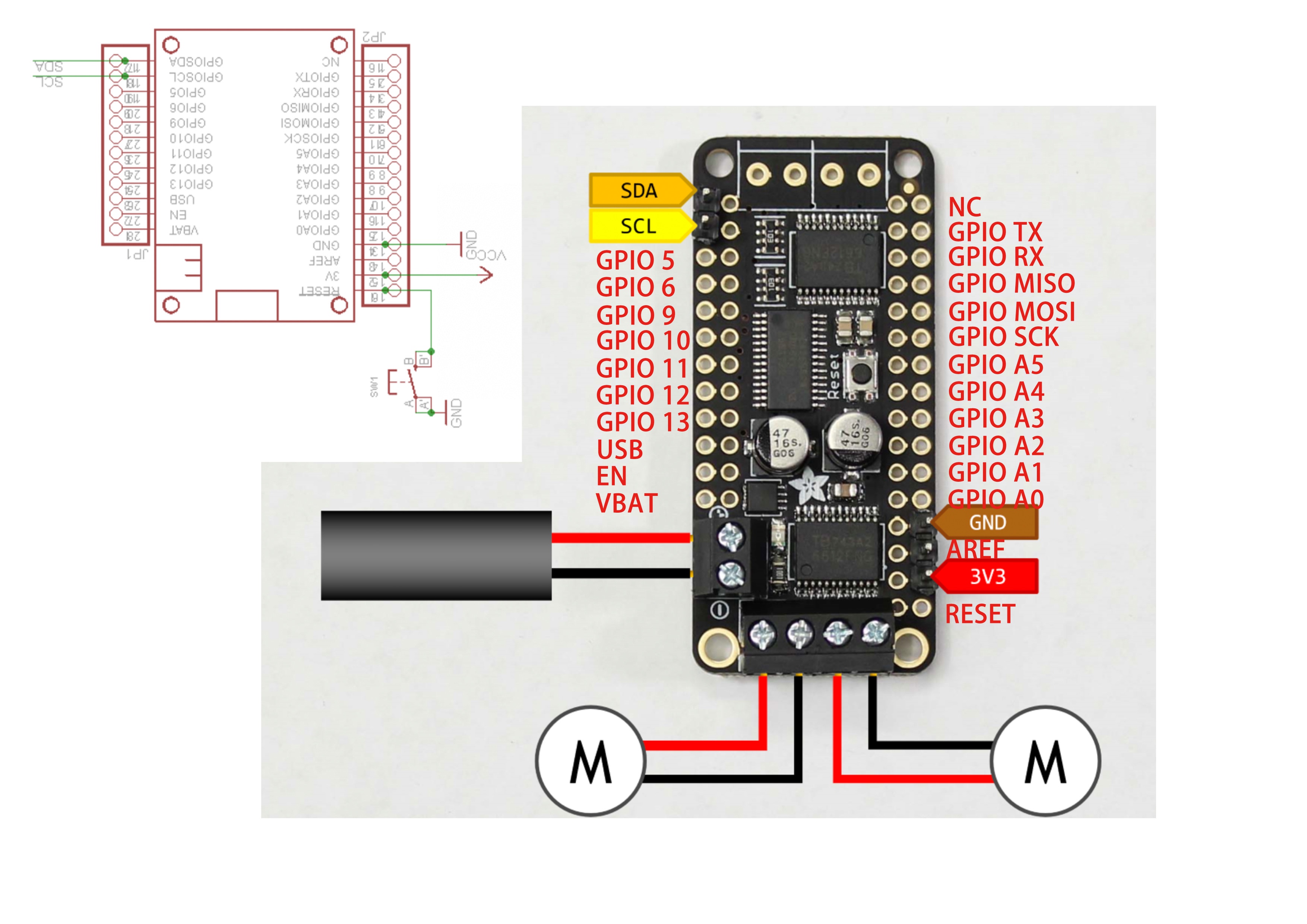
However, assembling JetBot only needs a few interfaces. This step only connects the MicroUSB data line as an external power line (3v3接_正极_、GND接_负极_).
Step – 3 Install TT Motor
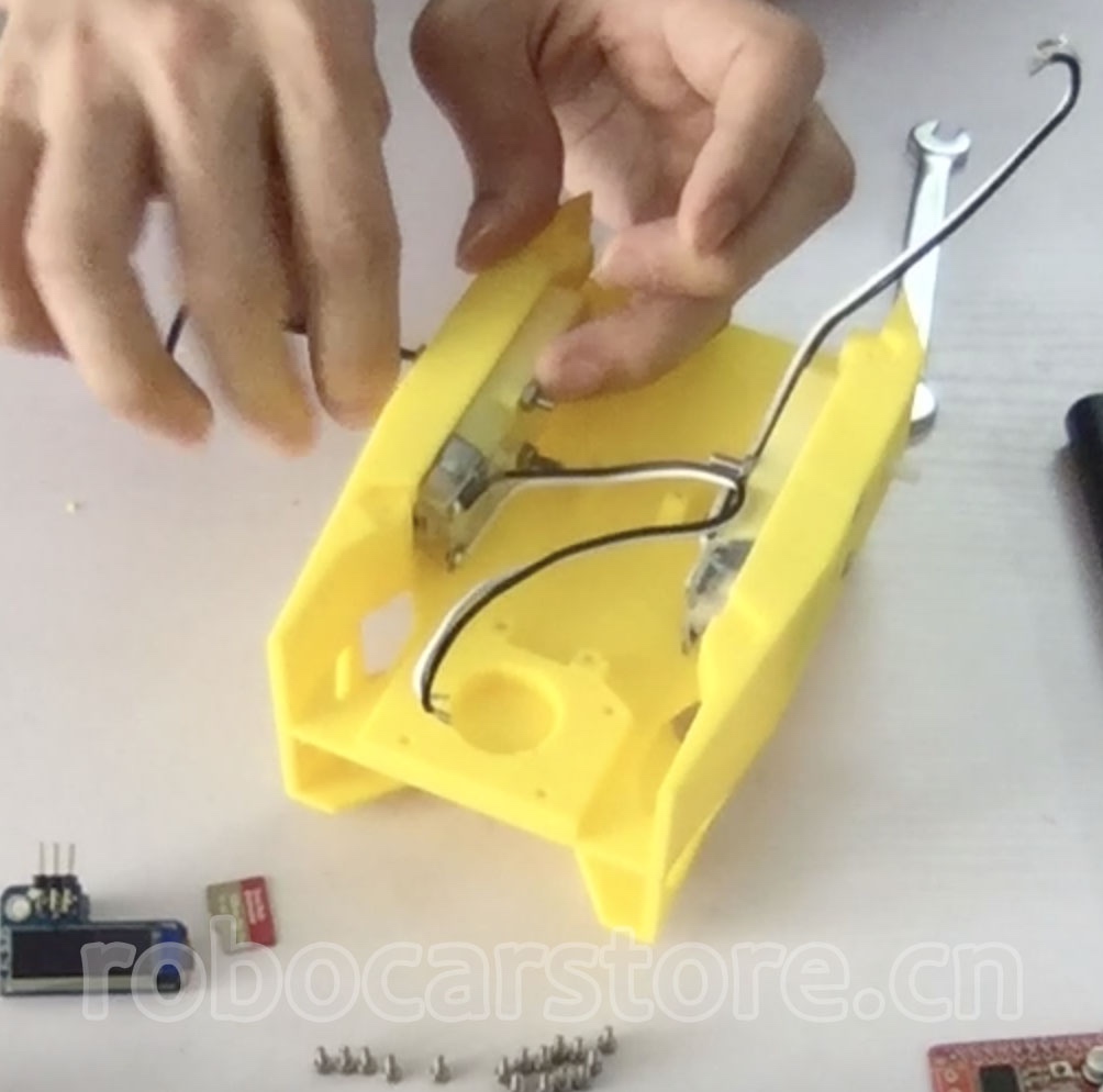
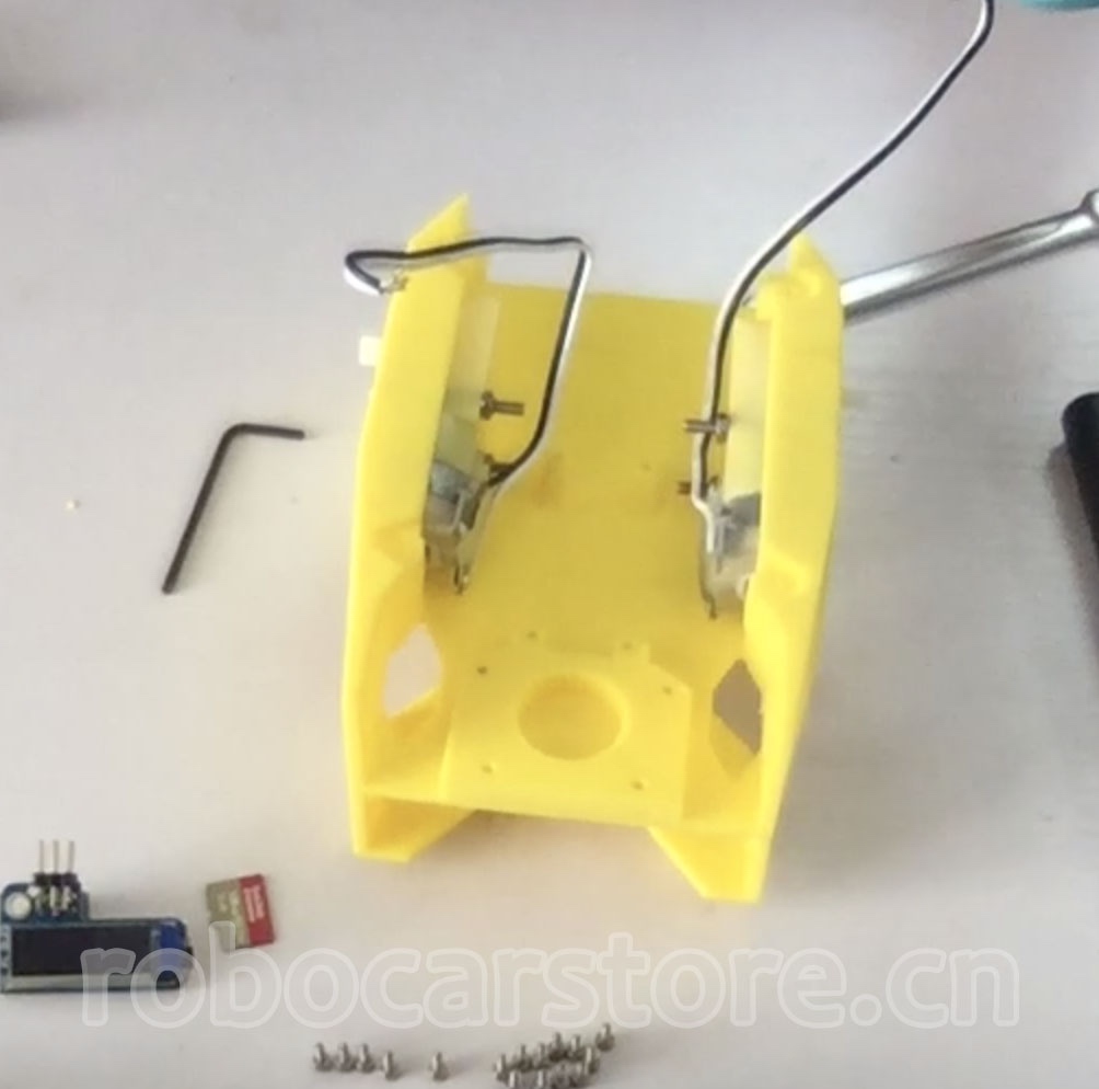
7,Install TT Motor
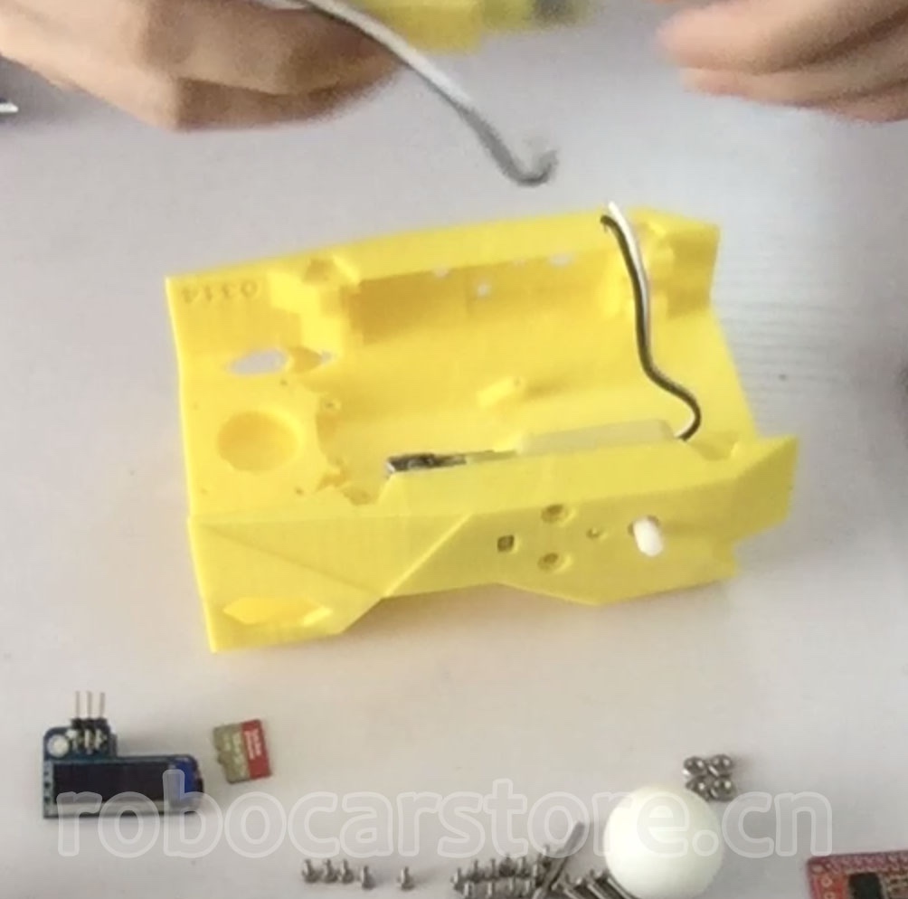
Prepare the 3D printed parts "chassis" (chassis.stl) and TT motor. Install the TT motor on the "chassis", fix it with M3 screws and M3 hex nuts, please be gentle, the 3D printed chassis is not as strong as you might think.
Step – 4 Install Motor Driver Module
8,Install Motor Driver Module on the "chassis"
First, use M2*6 self-tapping screws to install the motor driver module on the "chassis" (as shown in Figure 1).

Step – 5 TT Motor and Motor Driver Module Connection
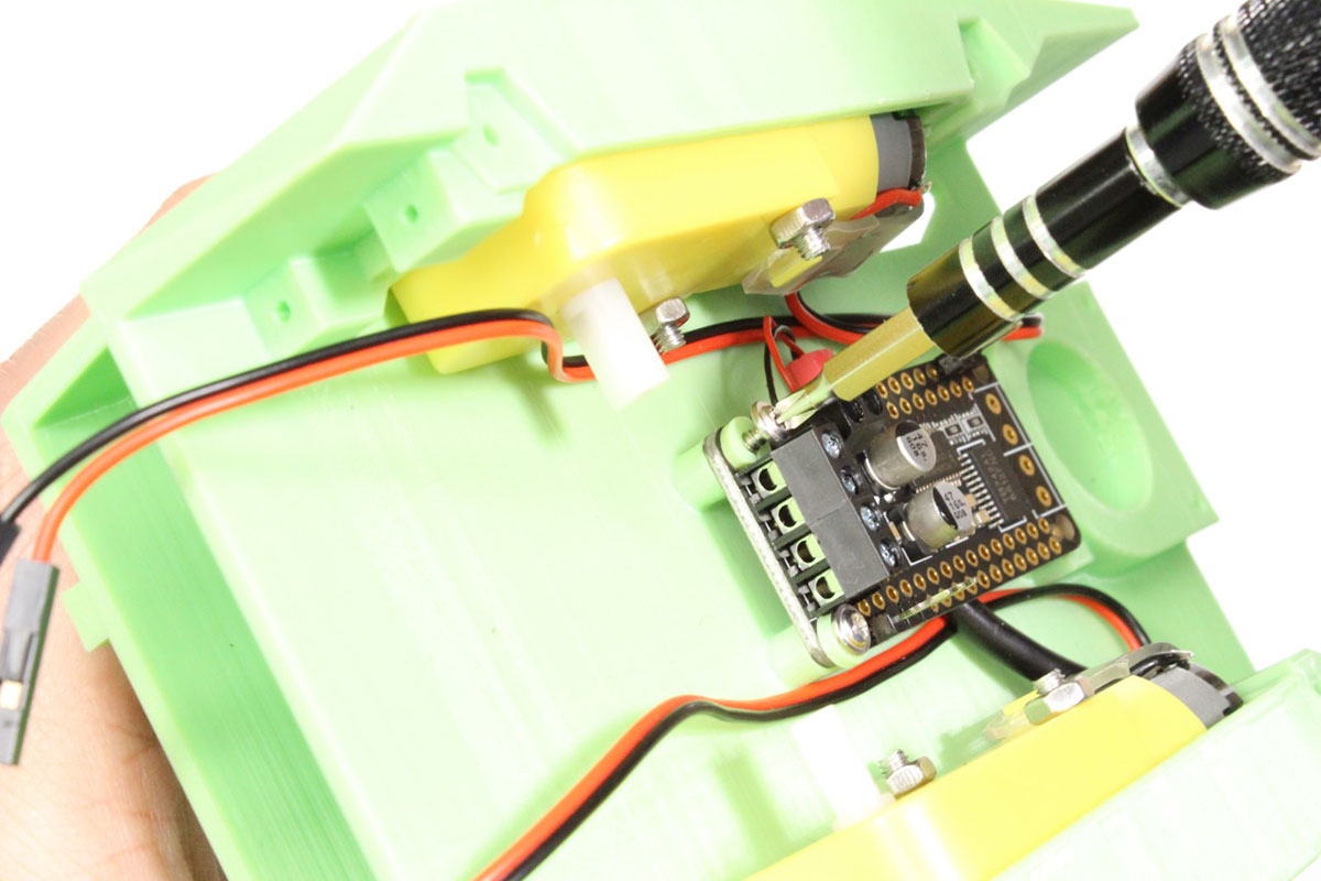
9,TT Motor and Motor Driver Module Connection
According to the wiring method shown in the figure, connect the TT motor to the driver module (even if you connect it incorrectly, it is not a big deal, you can check whether the direction is correct in the subsequent application instance, and then adjust it).
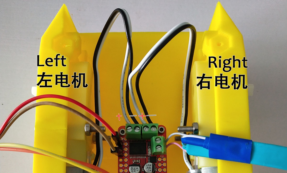
Note: In the installation video, the motor driver installation direction is different from the picture, please align with the direction shown in the article.
Step – 6 Install Wheels and Pre-connect Dupont Lines
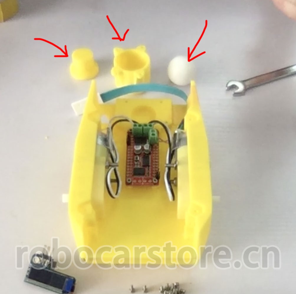
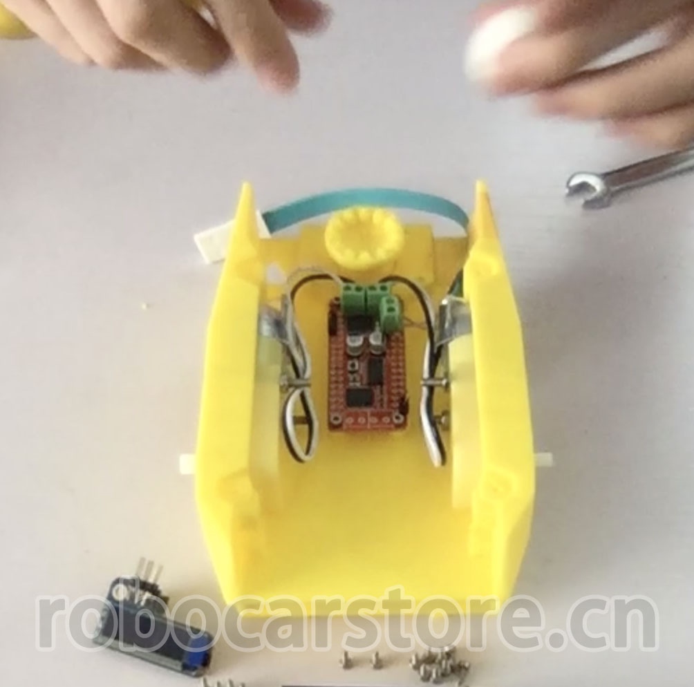
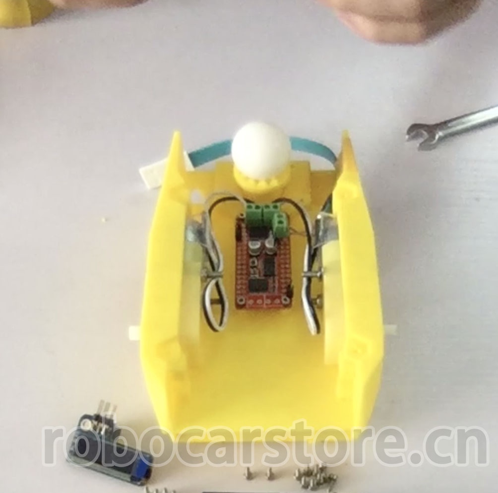
10,Install Omnidirectional Wheels
Prepare the "caster shroud 60mm" (caster_shroud_60mm.stl), "caster base 60mm" (caster_base_60mm.stl), and polyoxymethylene ball (POM ball). Place the "caster shroud 60mm" -> polyoxymethylene ball -> "caster base 60mm" in the groove of the chassis, and then use "M2*8 self-tapping screws" to fix it.
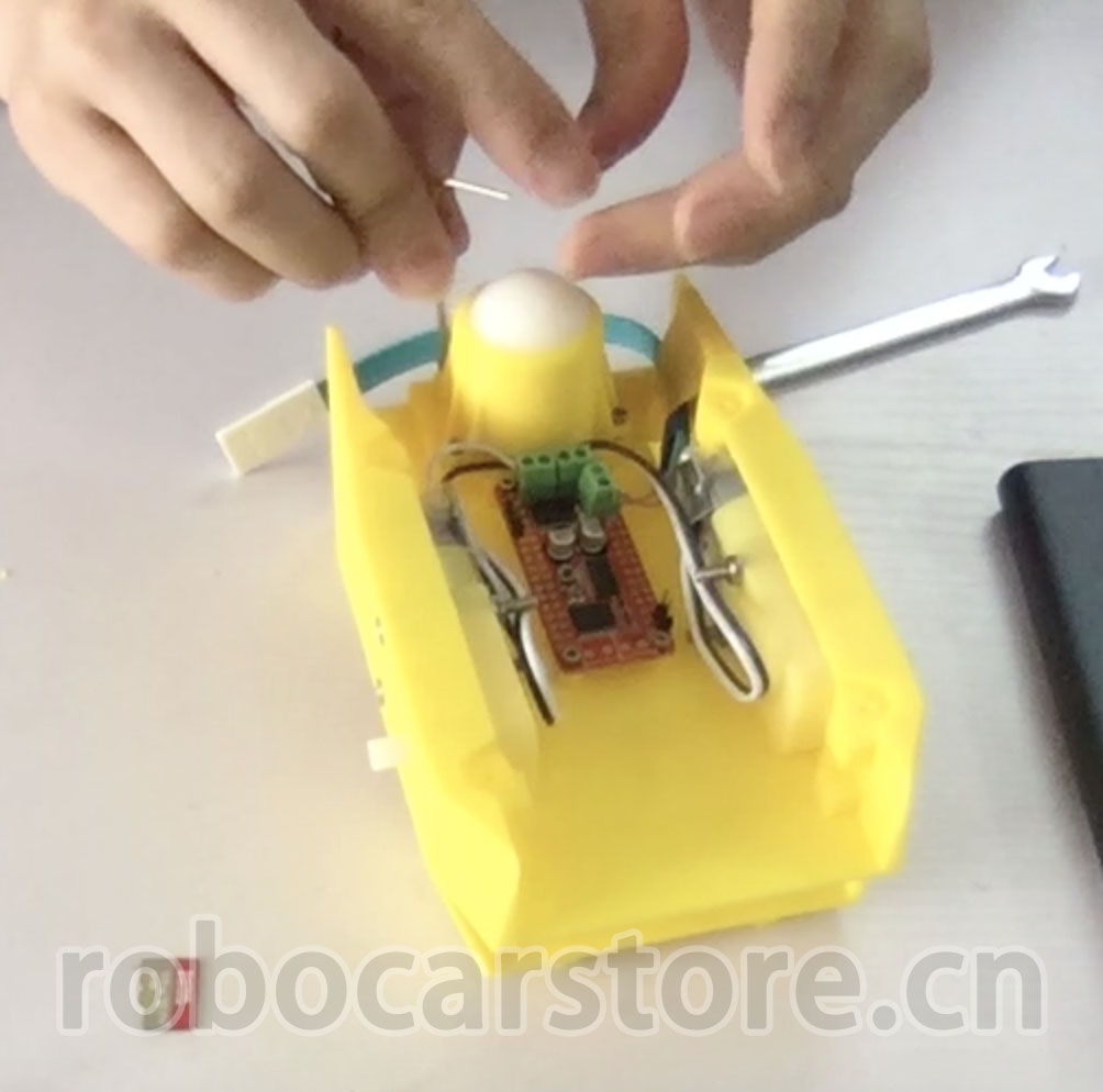
11,Motor Driver Module Pre-connect Dupont Lines
First, use Dupont lines to pre-connect the four pins on the motor driver module, which are: 3.3v, GND, SDA, SCL. Pre-connect it, wait for later use.
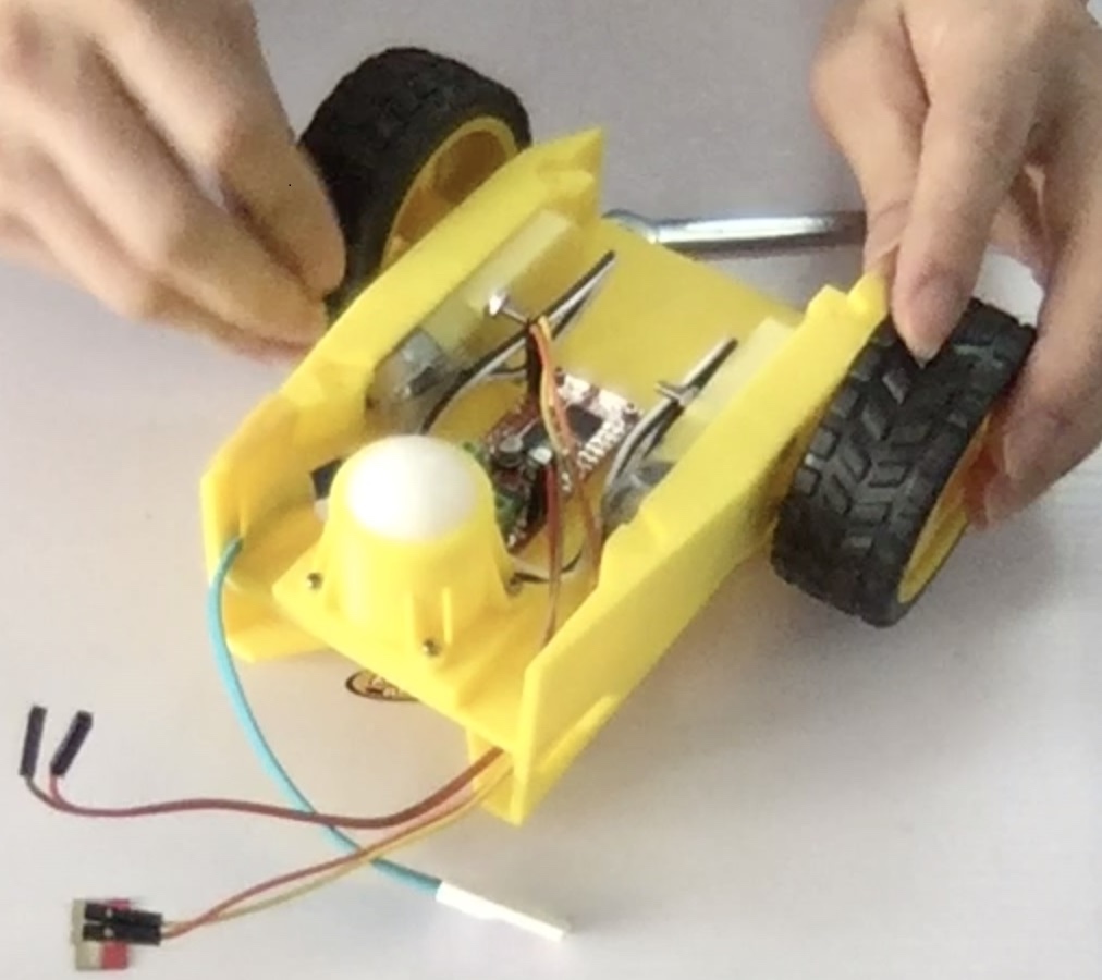
12,Install the Left and Right Wheels
Please install the wheels carefully, so as not to exert too much force and crush the "chassis".
Step – 7 Jetson Nano、OLED、电机驱动模块接线
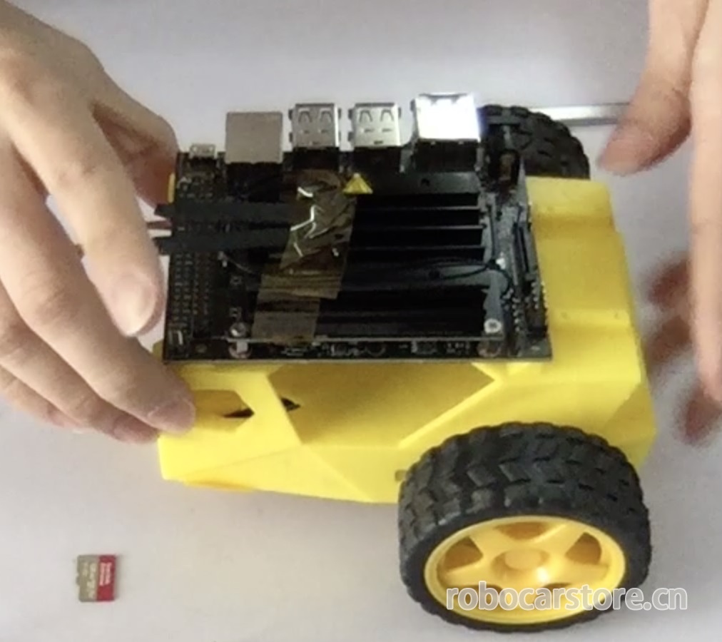
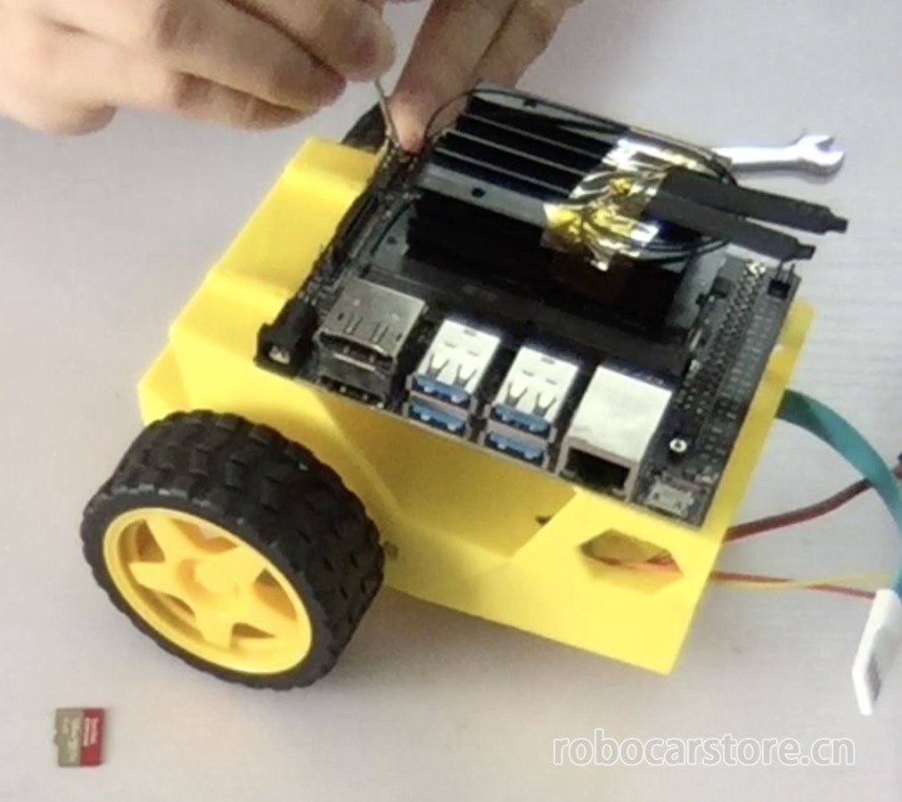
13,Fix the Jetson Nano on the "chassis"
Use M2*6 self-tapping screws to fix the Jetson Nano on the "chassis".
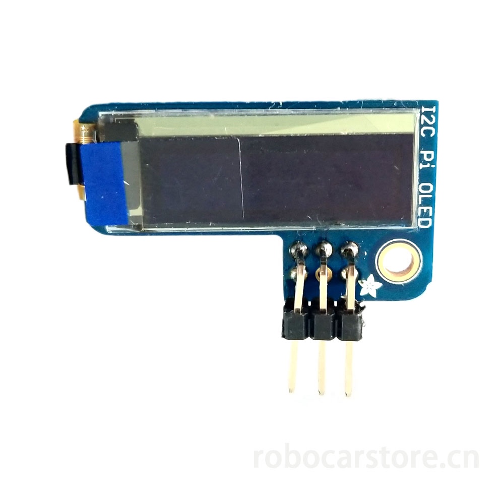
14,OLED Display Pre-wiring
Before connecting the wires, we need to use long double-row bent pins to weld the OLED Display (of course, you can also directly weld Dupont lines).
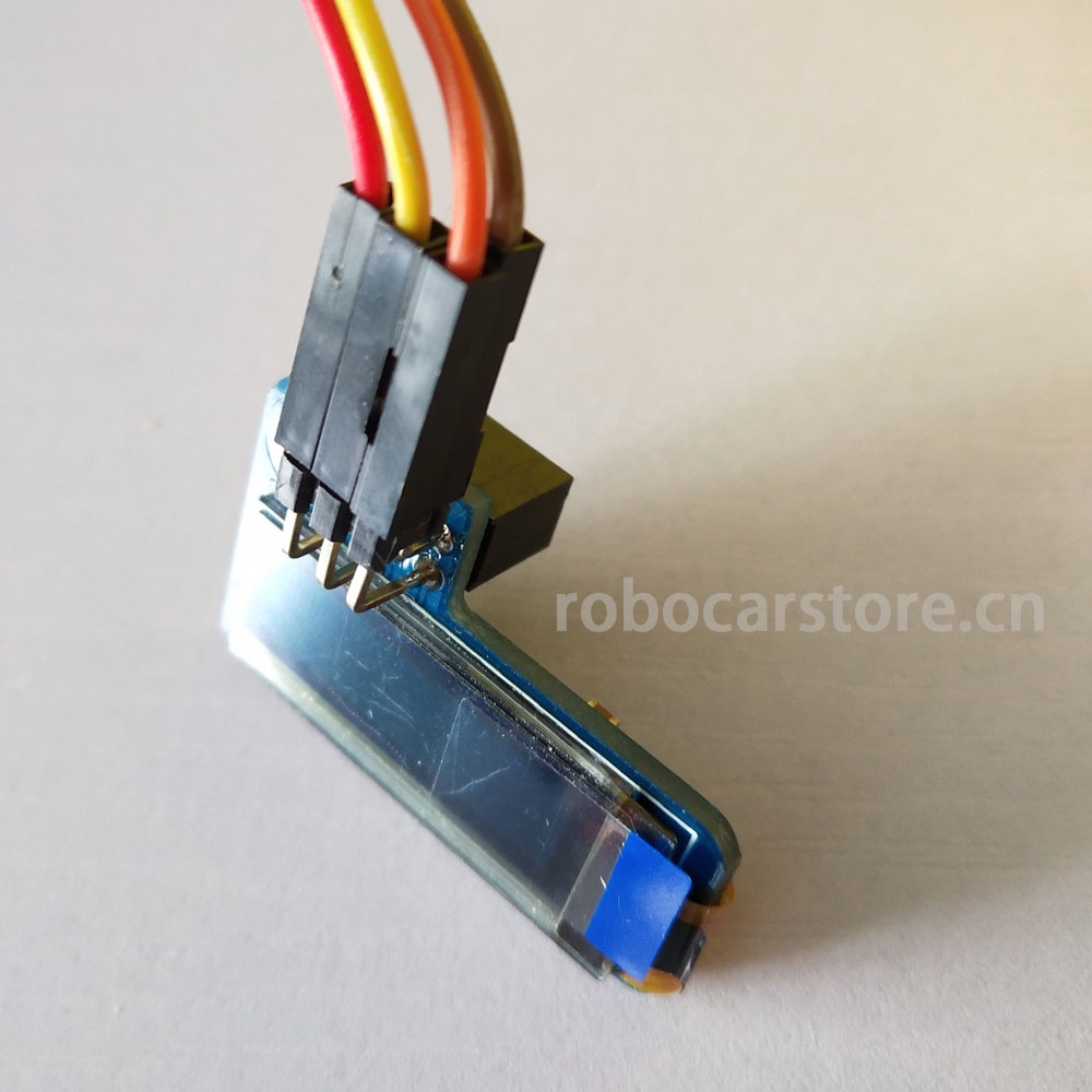
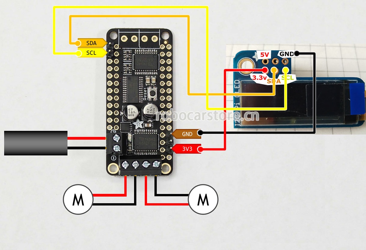
15,OLED Display and Motor Driver Module Connection
First, understand the pin of the OLED Display.
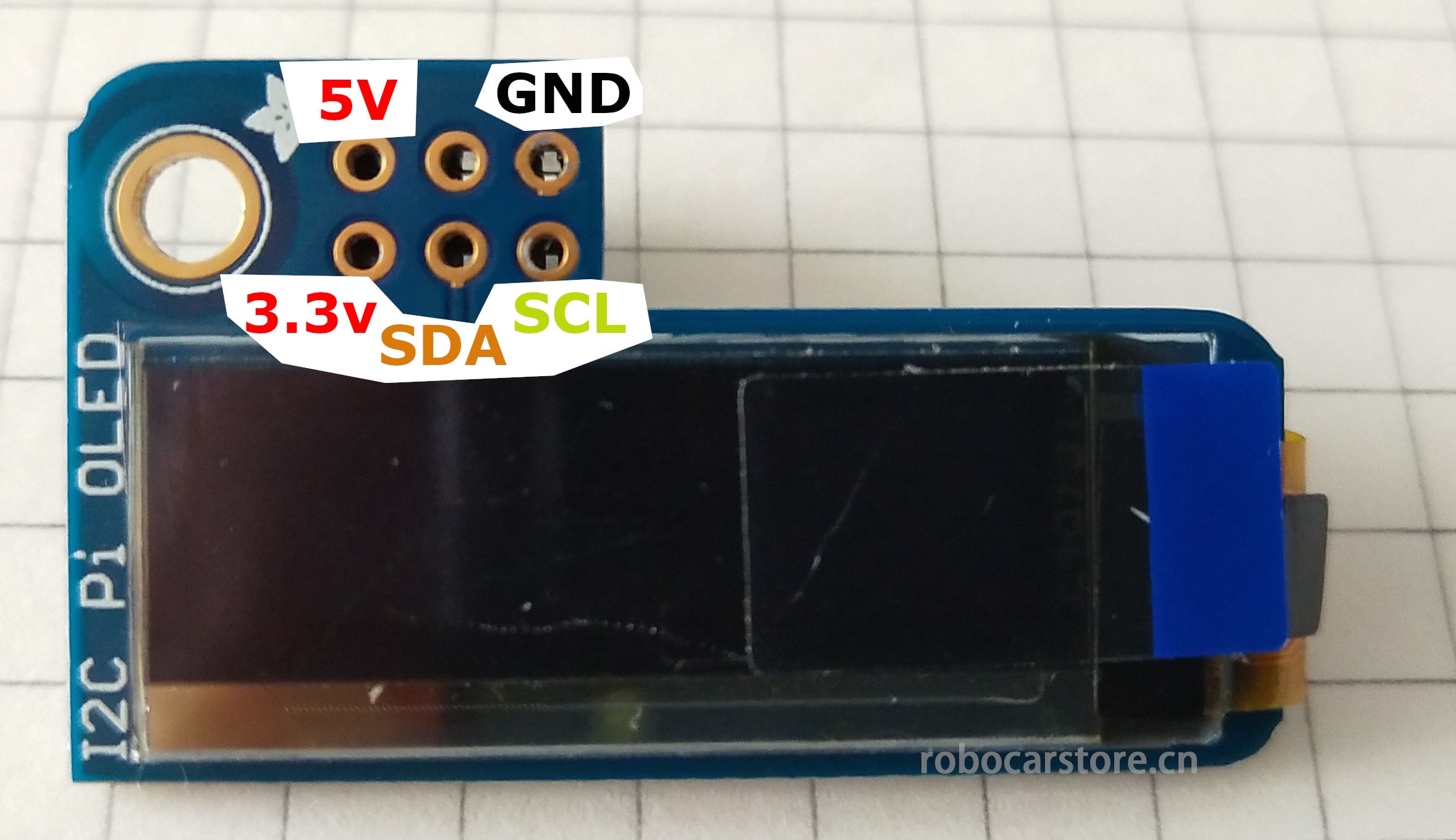
Then refer to the wiring diagram shown below, connect the OLED Display and the motor driver module.
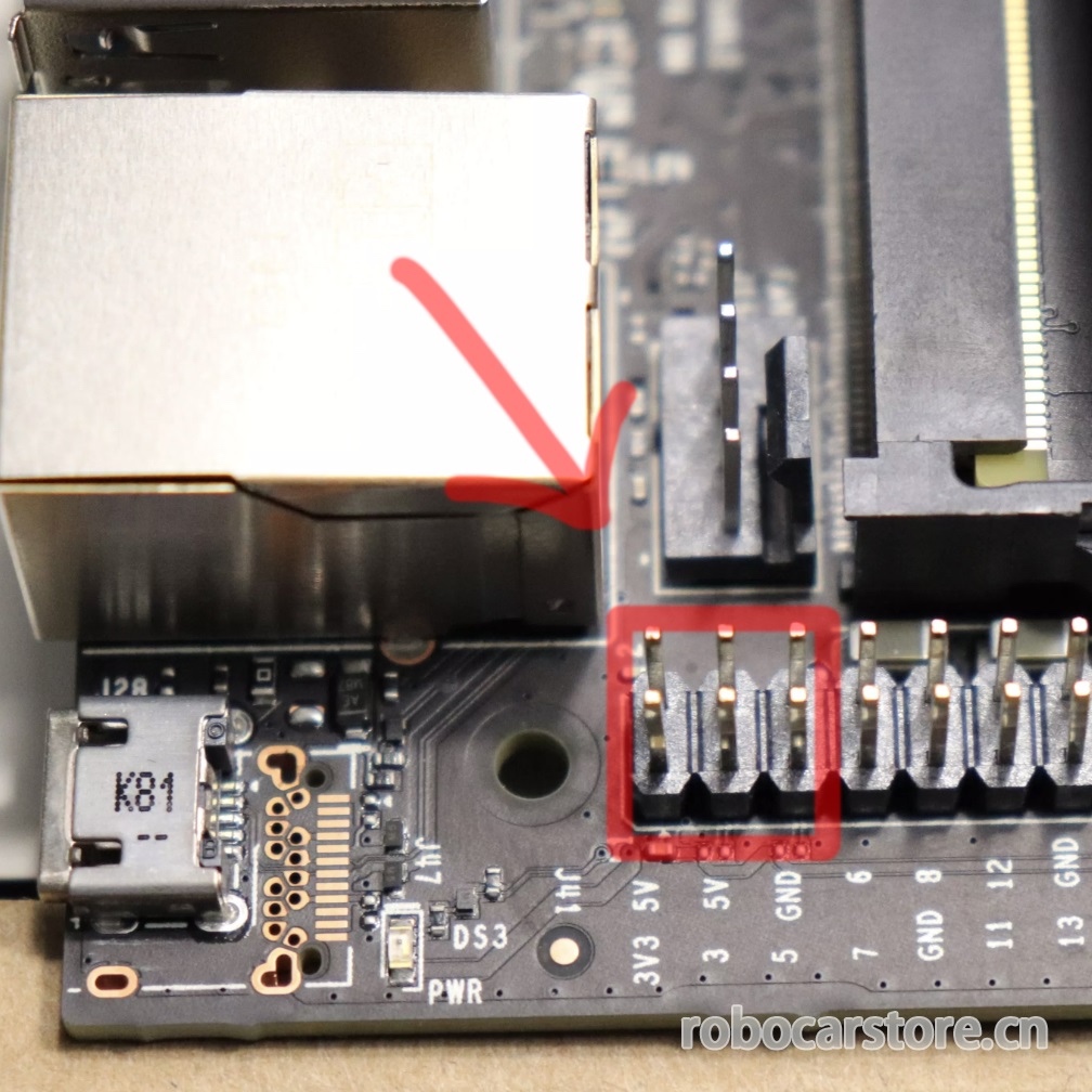
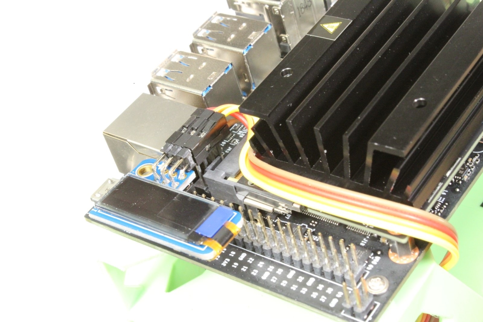
16,OLED and Jetson Nano Connection
Plug the OLED into the pins shown in the figure (the pins of the OLED Display are one-to-one corresponding), and install it according to Figure 2.
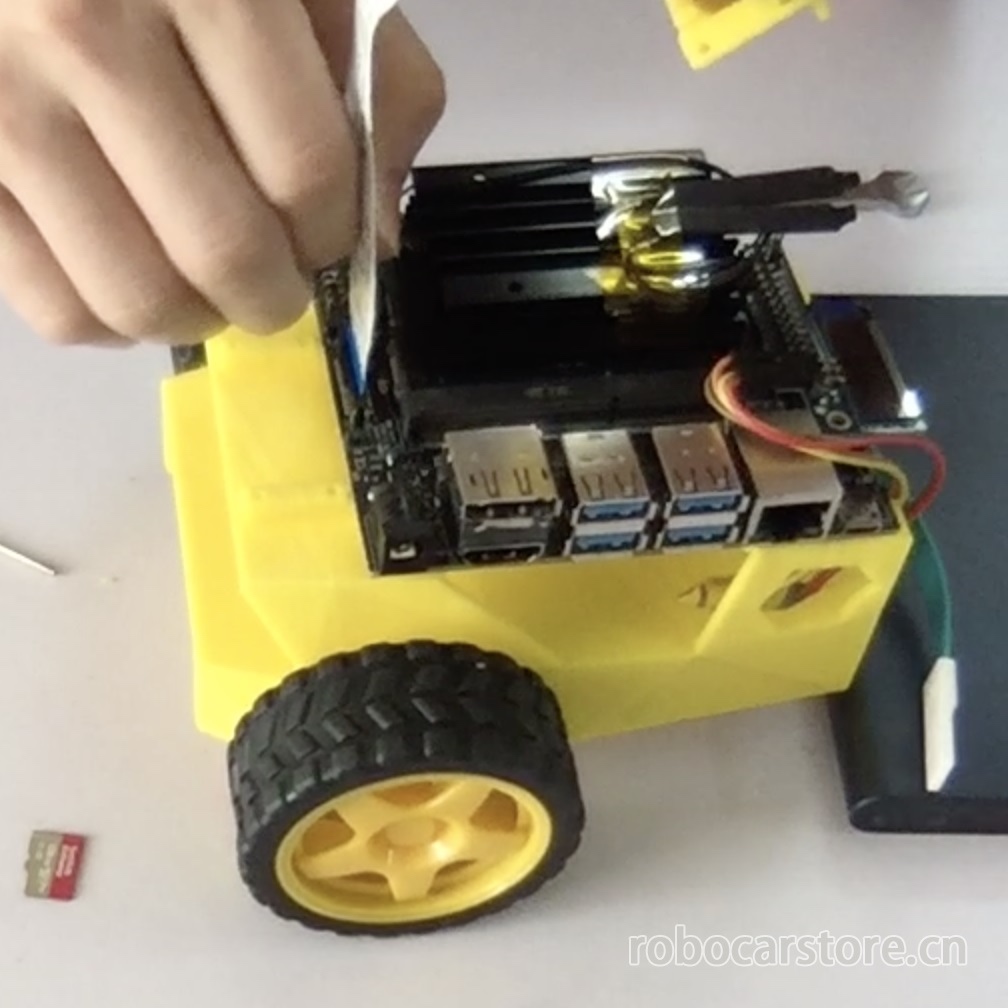
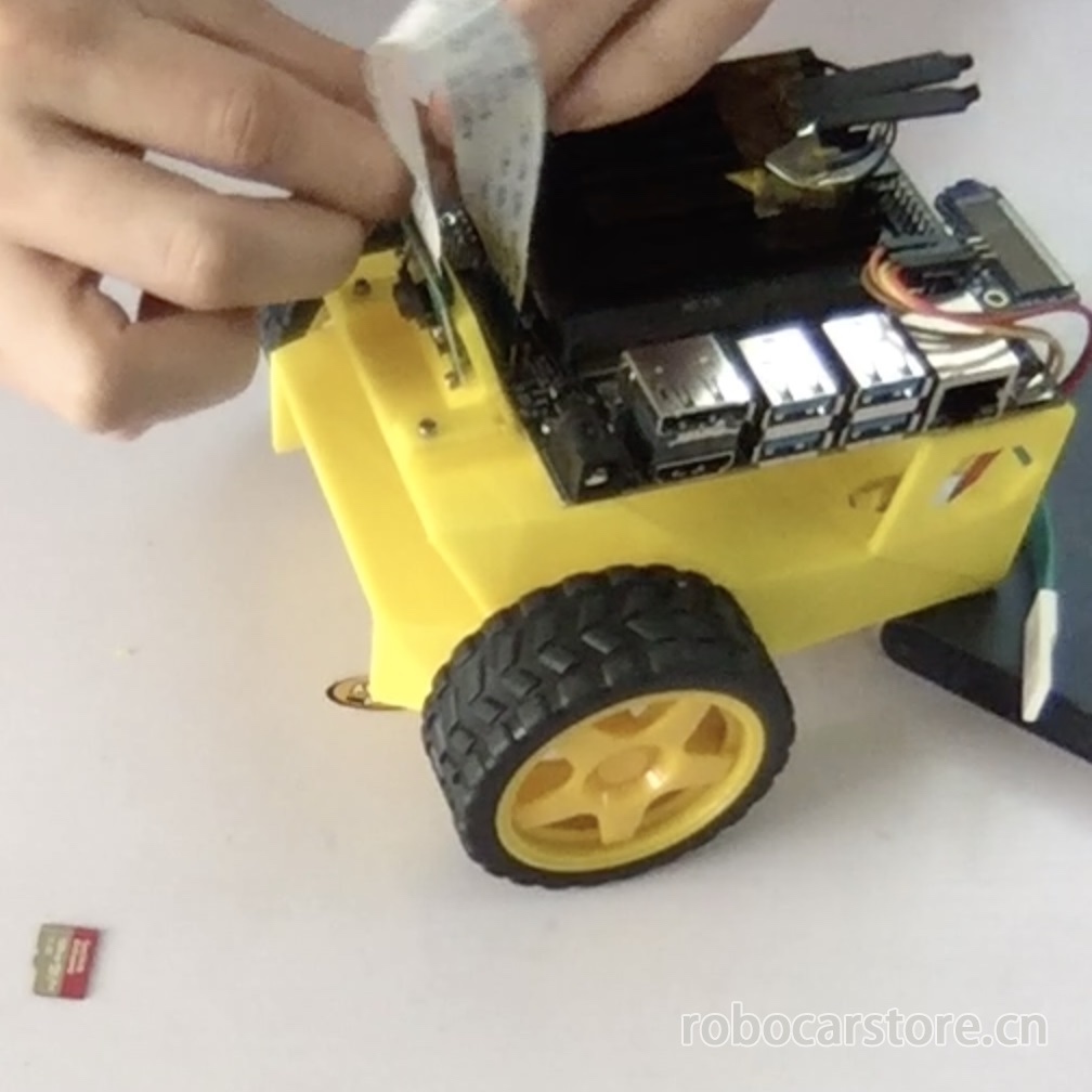
Step – 8 Install Pi V2 Camera
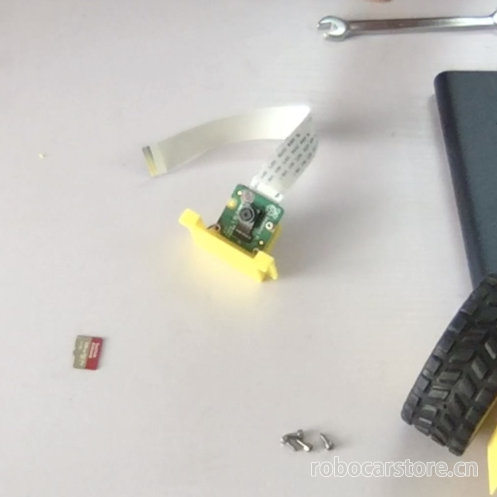
17,Fix the Camera on the "chassis"
First, use M2*6 self-tapping screws to fix the Pi V2 camera on the "camera mount" (camera_mount.stl), then connect the video line to the Jetson Nano, and finally use M2*6 self-tapping screws to fix the "camera mount" on the "chassis".
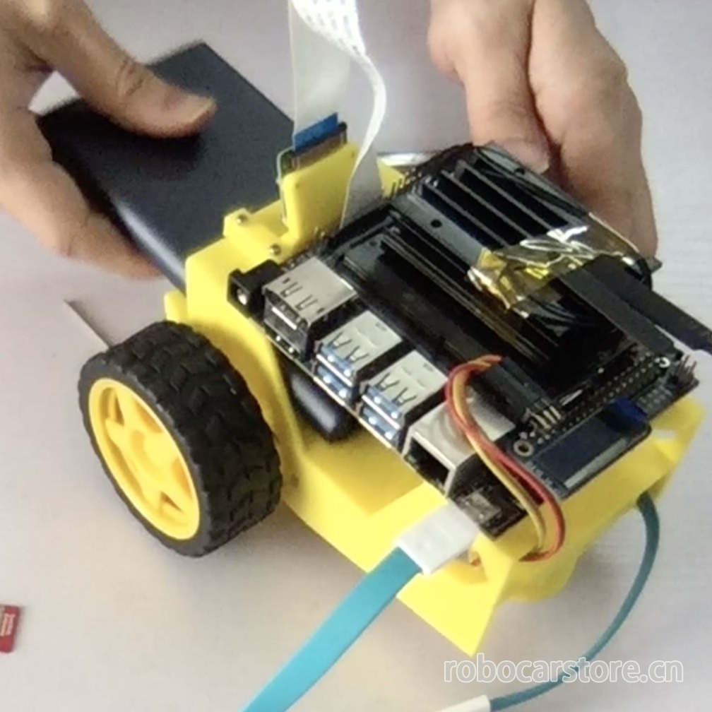
Step – 9 Install Mobile Power
18,Install the Mobile Power in the "chassis"
This is the last step, and also the simplest step. Put the mobile power into the power slot, and fix it with tape or 3M double-sided tape.
The next article will introduce how to burn the Jetson Nano system onto the MicroSD card.
to be continue……