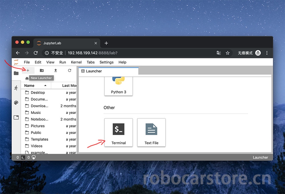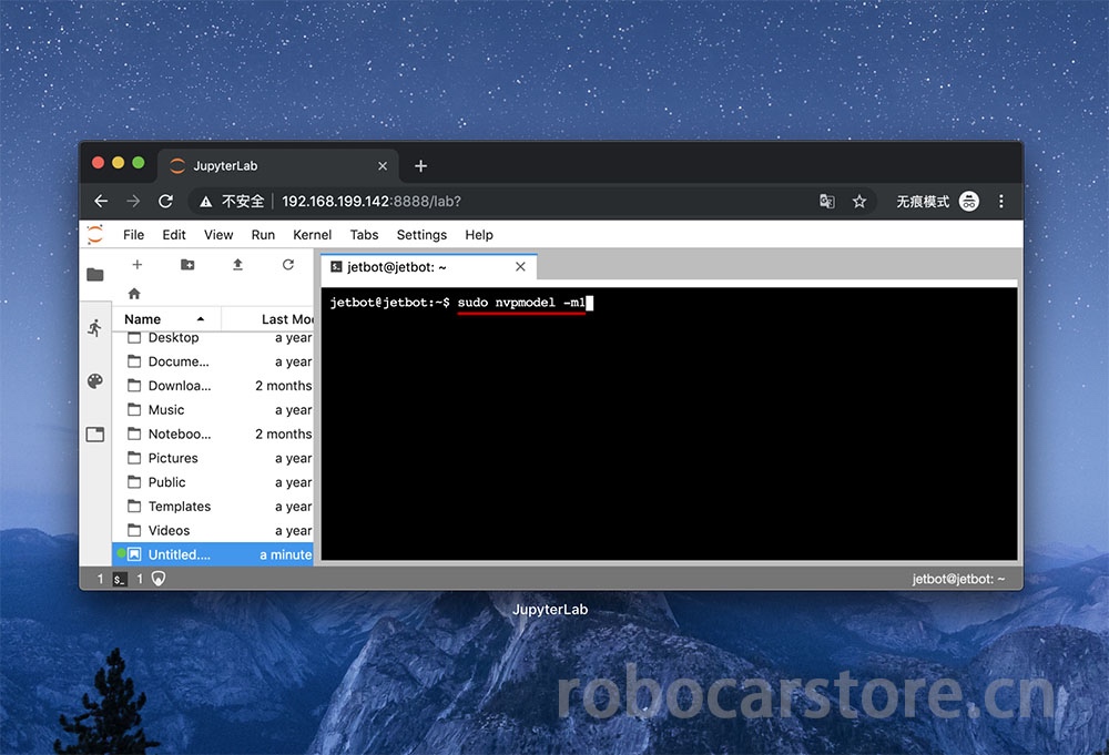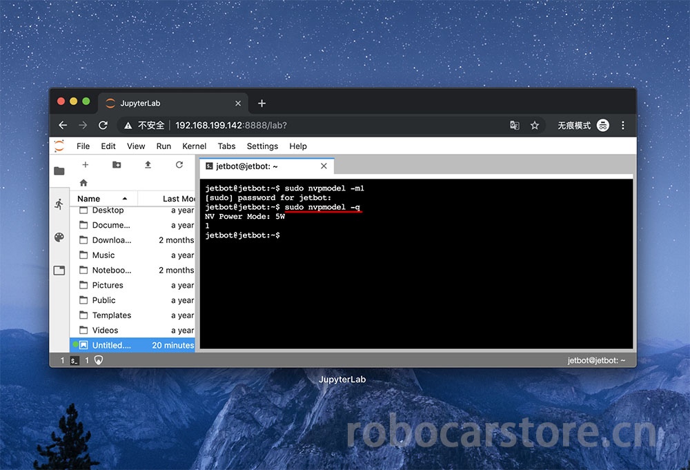
本篇详细讲解,如何使用jupyter lab在浏览器上控制你的JetBot,如何通过python进行对JetBot的编程。
我们在上一篇已经通过浏览器接触过jupyter lab并使用了一些功能,接下来我们会一直使用这个工具,所有我们有必要了解一下jupyter lab的界面,对不同区域的名称有个印象,将会让你在之后的操作更得心应手。
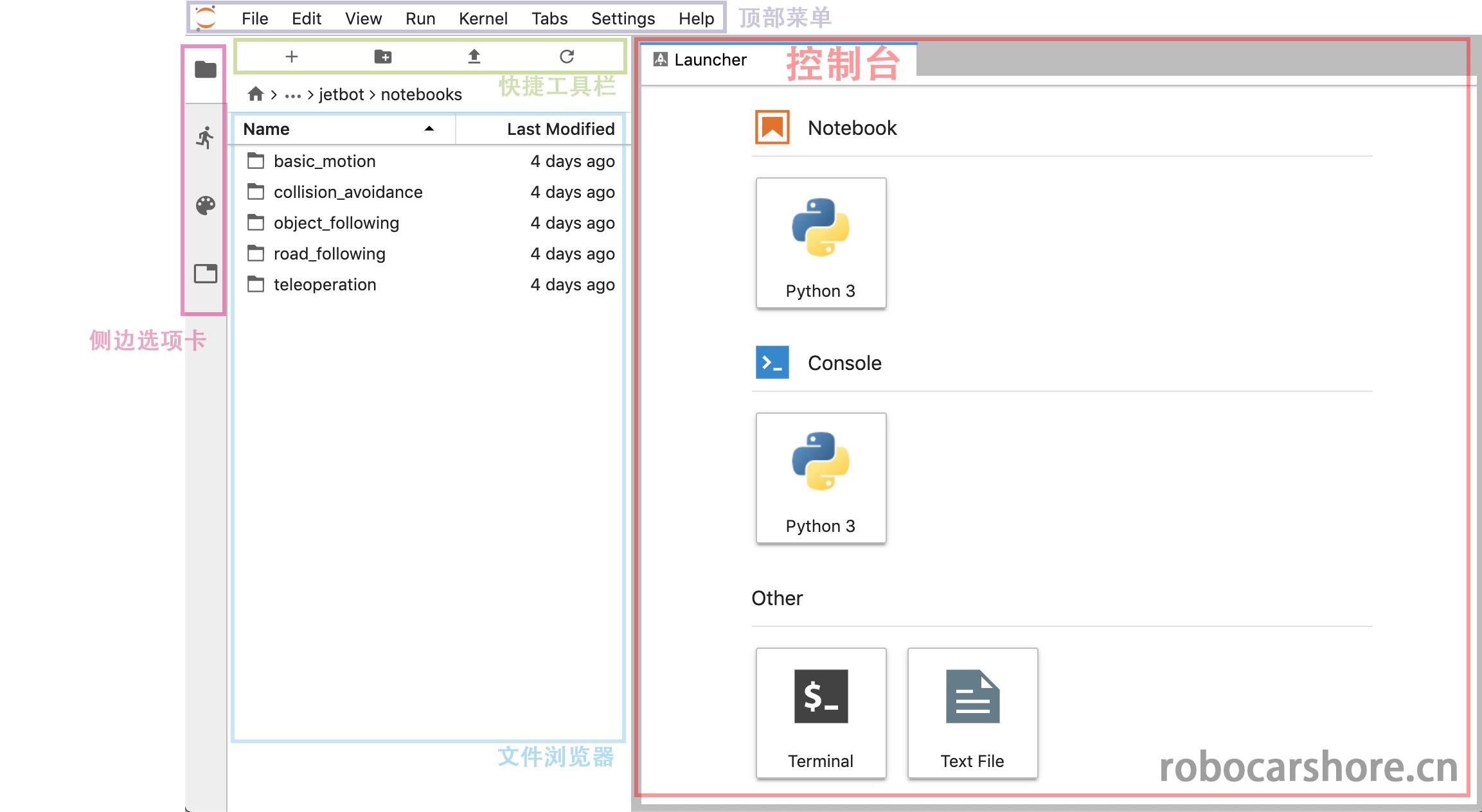
大概说明一下:
- 顶部菜单:包含了jupyter lab的所有操作,例如新建,保存,关闭运行中的内核等等
- 控制台:是一些快捷方式,在这里可以快速新建一个notebook,打开一个Terminal(终端,或者叫命令行)等等。
- 快捷工具栏:是一些快捷方式,从左到右,分别表示「新建一个控制台」、「创建文件夹」、「上传文件」、「刷新」
- 侧边选项卡:可以分别点开「文件浏览器」、「运行中的核心列表」、「命令列表」、「窗口列表」
接下来,会解读notebook里面python的语句什么意思,有什么用。
完整的notebook,请在这里浏览,样式更好看:
https://github.com/ling3ye/jetbot/blob/master/notebooks/basic_motion/basic_motion.ipynb
也可以下载此notebook,覆盖你的原有基础移动notebook。
欢迎来到基于jupyter lab的Jetbot编程界面。
这种类型文档我们称为“jupyter Notebook”,是一种集合文本,代码和图形显示于一身的文档。比起只有代码然后注释的方式更整齐简单明了, 如果你不熟悉‘Jupyter’ ,我建议你点击顶部菜单栏的「help」的下拉菜单,这有很多关于Jupyter lab的使用参考。
而在这个notebook,将会介绍JetBot的基础编程知识,以及如何使用python对你的JetBot进行编程。
准备开始JetBot为编程前,我们需要导入“Robot”类。这个类允许我们轻松控制JetBot的电机! 这包含在“jetbot”的_package_中。
如果你是一名Python新手,一个_package_就是一个包含代码文件的文件夹。
这些代码文件称为_modules_(模型)
要加载Robot类,请高亮显示下面的单元格,并按下ctrl + enter或上面的play图标。 这操作将执行单元格中所包含的代码。
现在已经加载Robot类,我们可以用一下语句初始化这个_instance_(实例)
现在我们已经创建了一个名为“Robot”的Robot实例,我们可以使用这个实例去控制我们的机器人(JetBot),执行下面的命令可使JetBot按最大速度的30%逆时针转动。
注意:这个命令将会使机器人发生移动,请保证有足够的平面给机器人移动,避免跌落损坏,或者干脆就放在地上。
很好,你现在应该见到JetBot在逆时针转动了!
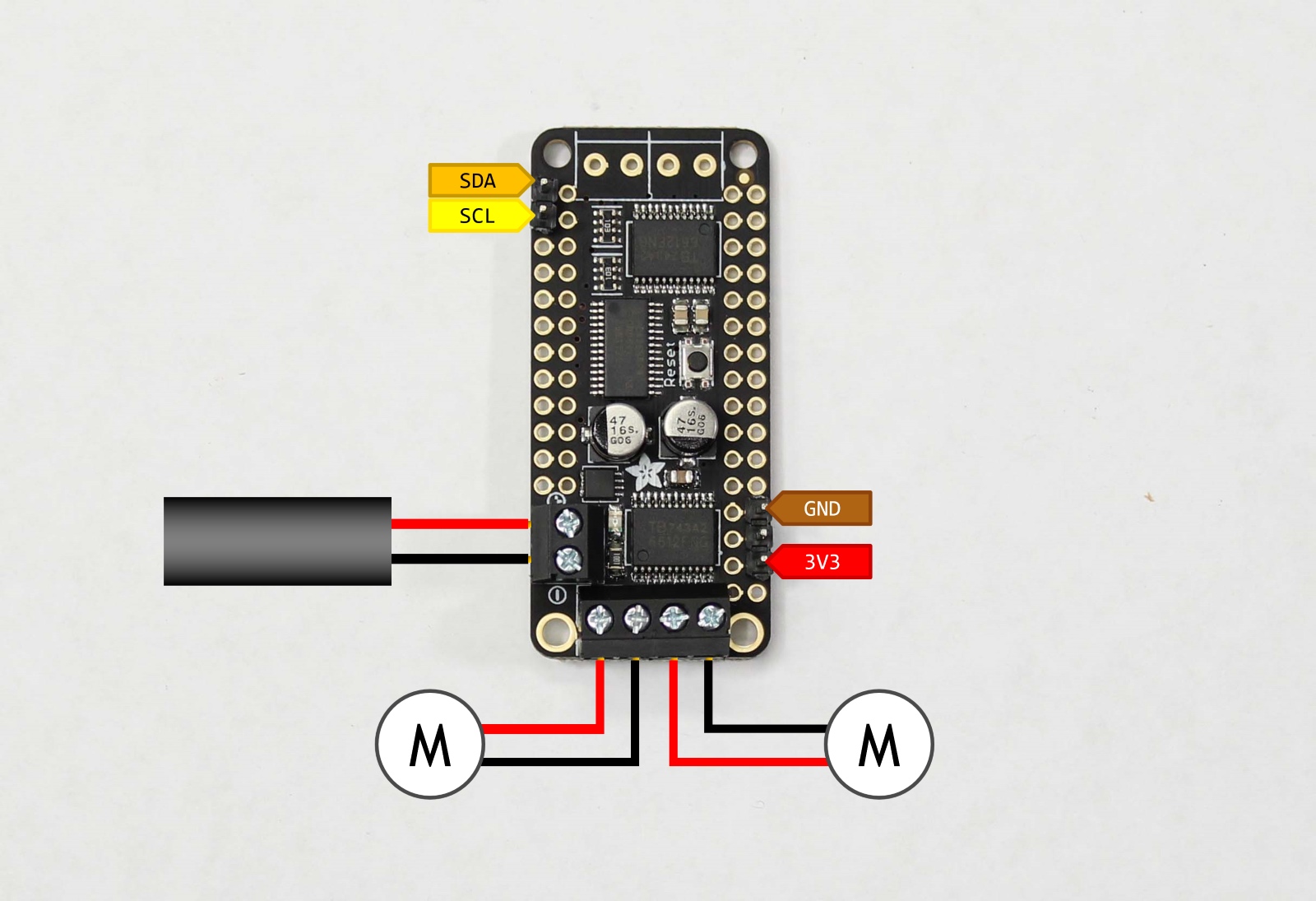
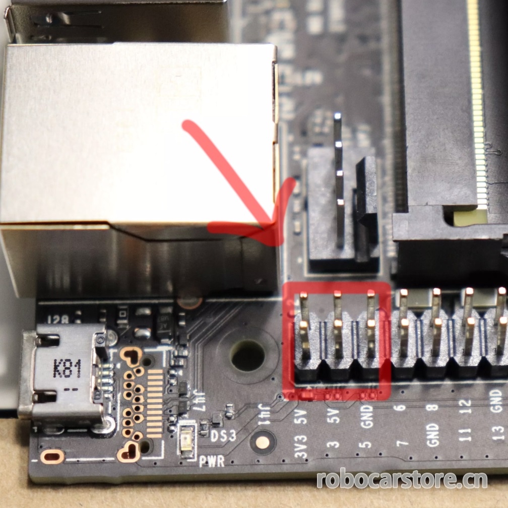
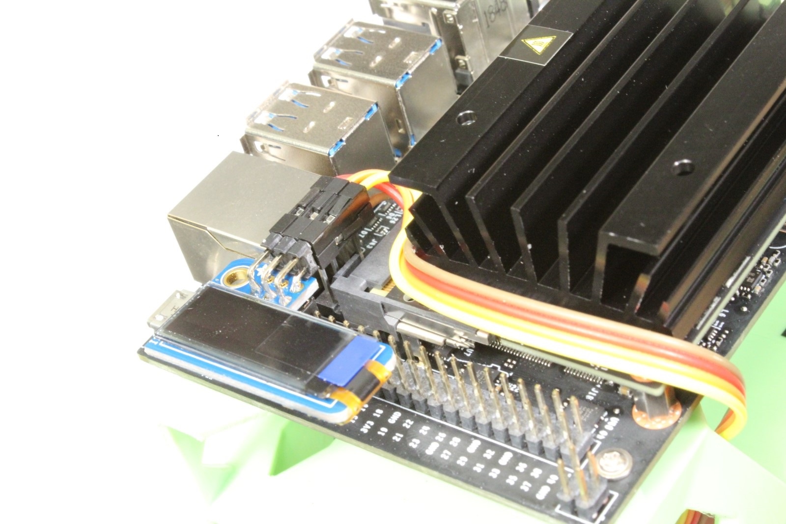
如果你的机器人没有向左转,这意味着其中一个或者两个电机接线出现问题。尝试关闭电源。找出不正确转动的电机,交换其正负极的接线。
提醒:请务必仔细检查接线,线的拔插也需要在切断电源的状态下进行。
现在,执行以下stop方法,就可以使机器人停止。
有时可能我们只想在一段时间内移动机器人,为此,我们可以使用Python的time package。执行以下代码,加载time
这个package定义了sleep函数,它导致代码执行时停止指定的秒数再运行下一个命令。 尝试以下命令的组合,使机器人仅向左转半秒钟。
非常好。你应该见到JetBot左转了一会儿,然后停了下来。
这个robot类也有right,forward和backwards方法。 尝试创建自己的单元格,参考之前的代码,让机器人以50%的速度向前移动一秒钟。
通过鼠标点击侧边的高亮条并按下“b”或按notebook上方的工具栏“+”图标来创建一个新单元格。 完成后,尝试输入您认为会使机器人以50%的速度向前移动一秒钟的代码,再执行验证所输入的代码是否正确。
上面我们看到了如何使用left,right等命令控制JetBot。但是如果我们想要单独设置每个电机速度怎么办?其实,有两种方法可以做到这一点。
第一种方法是调用set_motors方法。 例如,左转一秒,我们可以将左电机速度设置为30%,将右电机设置为60%,这将实现不同弧度的转向方式,如下所示。
robot.set_motors(0.3, 0.6)
非常好!你应该见到JetBot向左转。但实际上我们可以使用另一种方式来完成同样的事情。
在Robot类中还有两个名为left_motor和right_motor的属性,分别表示左电机和右电机的速度值。 这些属性是Motor类实例中的,每一个实例都包含一个value值。当这个value发生了变化就会触发events,重新分配电机的速度值。
所以在这个电机类中,我们附加的一个函数,只要值发生变化就会更新电机命令。因此,为了完成我们上面所做的完全相同的事情,我们可以执行以下操作。
robot.left_motor.value = 0.3

robot.right_motor.value = 0.6

robot.left_motor.value = 0.0

robot.right_motor.value = 0.0
您应该看到JetBot以相同的方式移动!
接下来介绍一个非常酷的功能,就是在Jupyter Notbooks中可以让我们在这个页面上制作一些图形小按钮(控件),而使用traitlets可以连接这些小部件进行控制操作。这样,我们就可以通过网页的按钮,去控制我们的小车,这将会变得非常方便好玩。
为了说明如何编写程序,我们先创建并显示两个用于控制电机的滑块。
import ipywidgets.widgets as widgets

from IPython.display import display

# create two sliders with range [-1.0, 1.0]

left_slider = widgets.FloatSlider(description='left', min=\-1.0, max=1.0, step=0.01, orientation='vertical')

right_slider = widgets.FloatSlider(description='right', min=\-1.0, max=1.0, step=0.01, orientation='vertical')

# create a horizontal box container to place the sliders next to eachother

slider_container = widgets.HBox([left_slider, right_slider])

# display the container in this cell's output

display(slider_container)
你应该看见两个
垂直的滑块显示在上面。
技巧提示:在Jupyter Lab,其实你可以把单元格弹出到其他窗口,例如这两个滑块。虽然不在同一窗口,但它仍然连接着这个notebook。具体操作是,鼠标移动到单元格(例如:滑块)上右键,选择「Creat new view for output」(为输出创建新窗口),然后拖动窗口到你满意的地方即可。
尝试单击并上下拖动滑块,会见到数值的变化。 请注意,当前我们移动滑块时JetBot的电机是没有任何反应的,那是因为我们还没有将它们连接到电机上! 下面我们将通过使用traitlets包中的link函数来实现。
left_link = traitlets.link((left_slider, 'value'), (robot.left_motor, 'value'))

right_link = traitlets.link((right_slider, 'value'), (robot.right_motor, 'value'))
现在尝试拖动滑块(要先慢慢地拖动,以免你的JetBot突然冲出边界造成损坏),您应该看到相应的电机在转动!
我们上面创建的link函数实际上创建了一个双向链接! 那意味着, 如果我们在其他地方设置电机值,滑块将会跟着更新! 尝试执行下面的代码块:
执行上面代码你应该看见滑块也发生了改变,响应了电机的速度值。如果我们要断开此连接,我们可以调用unlink方法逐一断开连接。
但是如果我们不想要一个双向的连接,比如说我们只想用滑块来显示电机的速度值,而不想用来控制,那么要实现这种功能,我们就可以使用dlink函数,左边是来源,右边是目标,(数据来源于电机,然后要显示在目标上)。
left_link = traitlets.dlink((robot.left_motor, 'value'), (left_slider, 'value'))

right_link = traitlets.dlink((robot.right_motor, 'value'), (right_slider, 'value'))
现在你可以上下移动滑块,你应该看到机器人的电机是没有一点反应。但当我们设置电机的速度值并执行的时候,滑块将会作出响应的数值更新。
另一种使用traitlets的方法是把函数附加到事件中(例如 forward) 。只要对对象发生改变,就会调用函数,并将传递改变了的一些信息,例如old 值和new值。
先让我们创建一些用来控制机器人的按钮显示在notebook上。
button_layout = widgets.Layout(width='100px', height='80px', align_self='center')

stop_button = widgets.Button(description='stop', button_style='danger', layout=button_layout)

forward_button = widgets.Button(description='forward',

backward_button = widgets.Button(description='backward', layout=button_layout)

left_button = widgets.Button(description='left', layout=button_layout)

right_button = widgets.Button(description='right', layout=button_layout)

middle_box = widgets.HBox([left_button, stop_button, right_button],

layout=widgets.Layout(align_self='center'))

controls_box = widgets.VBox([forward_button, middle_box, backward_button])
你应该看到上面显示的一组机器人控制按钮,但现在你点击按钮并不会做任何事。要做到控制,我们需要创建一些函数附加到按钮
on_click事件的中。
def step_forward(change):

def step_backward(change):
现在我们已经定义了那些函数,让我们把这些函数附加到每一个按钮的
on_click事件
# link buttons to actions

stop_button.on_click(stop)

forward_button.on_click(step_forward) backward_button.on_click(step_backward) left_button.on_click(step_left)

right_button.on_click(step_right)
执行以上代码,现在当你点击每一个按钮时,你应该看到JetBot都会对应作出移动。
这里我们显示怎么去使用’heartbeat’ package 来停止JetBot的的移动。这是检测JetBot与浏览器的连接是否还存在的简单方法。可以通过下面显示的滑块调整心跳周期(以秒为单位),如果两次心跳之内不能在浏览器之间往返通信的,那么心跳的’status‘ (状态)属性值将会设置为dead,一旦连接恢复连接,status属性将设置为alive。
from jetbot import Heartbeat

# this function will be called when heartbeat 'alive' status changes

def handle_heartbeat_status(change):

if change['new'] == Heartbeat.Status.dead:

heartbeat.observe(handle_heartbeat_status, names='status')

period_slider = widgets.FloatSlider(description='period', min=0.001, max=0.5, step=0.01, value=0.5)

traitlets.dlink((period_slider, 'value'), (heartbeat, 'period'))

display(period_slider, heartbeat.pulseout)
尝试执行以下这段代码去启动电机,然后降低滑块去看看发生了什么情况。你也可以尝试关闭你的机器人或者电脑。
这是一个简单的notebook例子,希望能对你的JetBot编程建立信心。